Ac power wiring / case size & panel mounting, Case size & panel mounting – Max Machinery 120 FLOW RATE & TOTAL INDICATOR User Manual
Page 6
Page 6
120-200-350 © 1993 (Rev 5/97) Max Machinery, Inc.
AC Power Wiring
A disconnect switch shall be included in the building installation. It shall be located in
close proximity to the equipment and within easy reach of the operator. (All switches and
circuit breakers must comply with IEC 947. Use a minimum of 18 gauge (1mm2, 600V)
and a maximum of 14 gauge (1.6mm2, 600V) wire for AC power wiring.
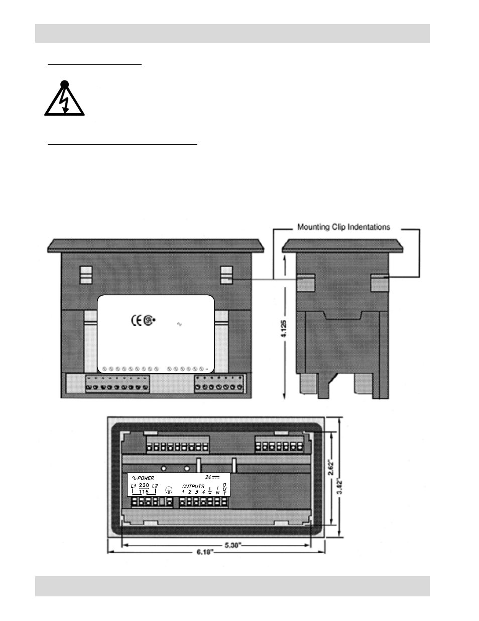
Case Size & Panel Mounting
To panel mount the Model 120, a hole 5.43" x 2.67" is required. Position the rubber gasket in back of
the indicator bezel. Place the indicator in the mounting hole. Noting the screw orientation molded into
the center of the mounting clips, start the four screws. Snap the two clips into the case indentations.
Tighten the screws until the indicator is secure.
AC POWER WIRING / CASE SIZE & PANEL MOUNTING
Model No.: 120-200
Serial No.: B600958
Part No.: 57630-449-05
Data Code: 09/26/96
(004)
Input Power: 24VDC/4A
115/230V
50/60HZ .2/.1A
TUV File# E9671839.02
MAX MACHINERY, INC.
HEALDSBURG, CA 95448
707-433-7281
MADE IN USA
LR20733
Control Inputs
1 2 3 4 5
4-20 MA OUT
4-20 MA OUT
T
O
T
ALIZER INHIBIT
COMMON
FLOW SIGNAL
COMMON
RS485 COM
RS485 -
RS485 +
COMMON
COMMON