Programming – Max Machinery 120 FLOW RATE & TOTAL INDICATOR User Manual
Page 13
120-200-350 © 1993 (Rev 5/97) Max Machinery, Inc.
Page 13
Sub Menu 13 - 4-20 mA Output Calibration
To calibrate the analog output signal, first turn off all power and then connect the analog output “+”
terminal to the 24 VDC out terminal of the control. Connect the analog output “-” terminal to a
current meter and connect the other end of the current meter to the 24 VDC ground terminal. Turn
power back on and select menu 13. Press the Clear key to start the calibration process and use the
Left / Right arrow keys to adjust the current to 4 mA, then press the Enter key to enter the 4 mA
calibration point. Use the up arrow key to select the 20 mA setpoint. Press the Clear key to start the
calibration process and use the Left / Right arrow keys to adjust the current to 20 mA, then press the
Enter key to enter the 20 mA calibration point.
Sub Menu 14 - Rate 4 - 20 mA Output Range
The rate output range is programmed at both the 4 mA and 20 mA points. This permits analog rate
indications from 0 to full scale of the digitally displayed rate or a portion of the rate range. Use the up
arrow key to select the 4 mA or 20 mA setpoints and then use the Clear, number and Enter keys to
enter a rate value at each setpoint.
Sub Menu 15 - Diagnostics
The diagnostics allow the user to test the indicator display and internal memory. Press the up arrow
key for display test 1. Each of the display’s 16 characters will go to 8 with the decimal point lit. Press
the up arrow key for display test 2. Each character will go to *. Press the up arrow key for the internal
memory test. The display will read TEST IN PROCESS for three seconds while the tests are being
run. The display will read SYSTEM TEST OK for two seconds, then go back to DIAGNOSTICS if
no memory errors were detected. If the unit detects a memory error, the display will hold an error
message. The error messages are:
ROM ERROR
INTERNAL ERROR
EXTERNAL ERROR
These errors are non-recoverable. It is possible that electrical noise caused the diagnostic failure, so
the power to the unit should be cycled (turned off and then turned back on). The memory tests are
always performed at power up. If the same test fails at power up, the unit likely needs repair. If a
different test fails, or if the unit powers up normally, it is likely that the unit is experiencing electrical
noise problems. Note that the error messages for the power up memory tests may be different than the
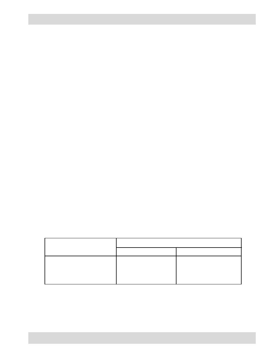
error messages for the program mode diagnostic memory tests. The following table lists each test
failure and its associated error message in each test mode.
Note that the power up diagnostic memory test performs an additional test, the external RAM
checksum. If the calculated checksum of the external RAM (the memory which holds the user
program) does not match the stored checksum, the user program has been corrupted and the message
STORE ERROR appears on the display. This error is recoverable by pressing the Reset key. The
message VERIFY PGM DATA then appears on the display for one second to prompt the user to locate
and correct program mode item(s) which may have been altered.
PROGRAMMING
Test Failure
ROM checksum error
Int. RAM bit error
Ext. RAM bit error
EXT. RAM checksum error
ROM ERROR
INTERNAL ERROR
EXTERNAL ERROR
N/A
ROM ERROR
RAM ERROR
EXT RAM ERROR
STORE ERROR
Error Message
Program Diagnostics
Power Up Diagnostics