Mallory Ignition ACCEL 275_300 digital ignition 49275_49300 User Manual
Page 4
CHECKING FOR SPARK
If triggering the ignition with the white wire:
1. Make sure the ignition switch is in the "OFF" position.
2. Remove the spark plug coil wire from the distributor cap
and set the terminal approximately 1/4" from ground.
3. Disconnect the 275+ or 300+ Ignition Control’s white wire
from the distributor’s points or ignition amplifier.
4. Turn the ignition to the ON position. Do not crank
the engine.
5. Tap the white wire to ground several times. Each time you
pull the wire from ground, a spark should jump from the
coil wire to ground. If spark is present, the ignition is work-
ing properly. If there is no spark, skip to Step 6 below.
If Triggering With the Magnetic Pickup:
1. Make sure the ignition switch is in the OFF position.
2. Remove the spark plug coil wire from the distributor cap
and set the terminal approximately 1/4" from ground.
3. Disconnect the 275+ or 300+ Ignition Controls magnetic
pickup wires from the distributor.
4. Turn the ignition to the ON position. Do not crank
the engine.
5. With a small jumper wire, short the 275+ or 300+ Ignition
Control’s green and violet magnetic pickup wires together.
Each time you break this short, a spark should jump from
the coil wire to ground. If spark is present, the ignition is
working properly. If there is no spark skip to Step 6 below.
6. If there is no spark:
A. Inspect all of the wiring.
B. Substitute another coil and repeat the test. If there
is now spark, the coil is at fault.
C. If there is still no spark, check to make sure there
is 12 volts on the small red wire from the 275+ or
300+ Ignition Controls when the key is in the ON
position. If 12 volts is not present, find another
switched 12 volts source and repeat the test.
D. If after following the test procedures and
inspecting all of the wiring there is still no spark,
the 275+ or 300+ Ignition Controls are in need of
repair. See the Warranty and Service section
for information.
ACCEL 300+ RPM LIMITER SETTINGS ONLY
Note the sticker attached to the front of the 300+. This sticker
shows settings for number of cylinders and RPM limits. In
case the sticker becomes damaged or otherwise unreadable,
the settings are shown at right.
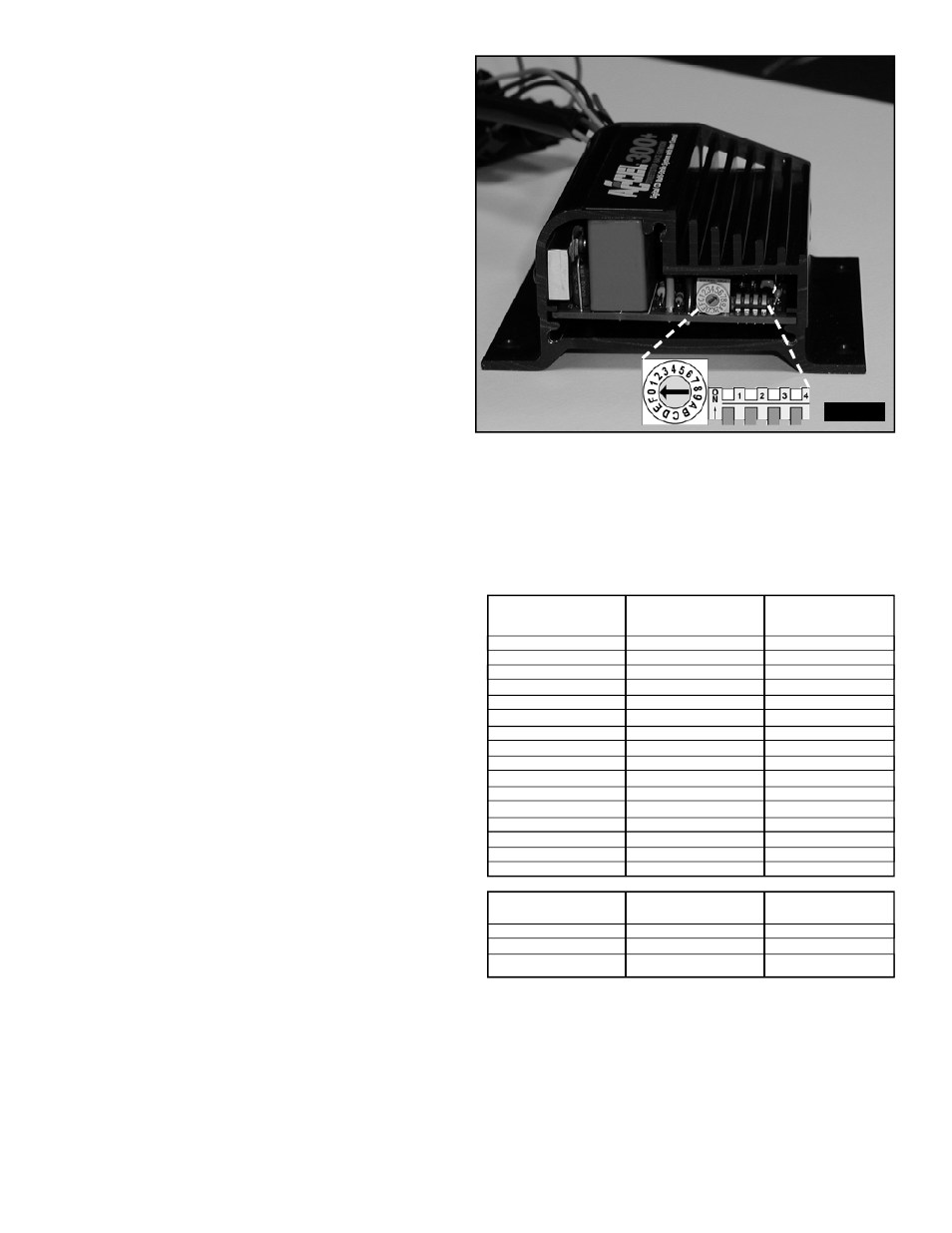
ACCEL 300+ Cylinder Selection Only
Your 300+ Ignition comes from the factory set up for
8-cylinder operation. If you want to use this ignition with a
4- or 6-cylinder engine, you must first remove the three
screws that hold the end plate opposite the wire harness
end. Once the end plate is removed, you will see the end of
the circuit board. Look for the four selection DIP switches.
To select 4-cylinder mode, move DIP switch #2 up. To select
6-cylinder mode, move DIP switch #3 up. See Figure #2.
Setting Switch #4
This switch should be set DOWN for normal operation. If you
are using a compatible external RPM limiter, such as the
ACCEL 375+ Multi-Function Accessory, this switch should be
set to the UP position.
CAUTION: Using the ACCEL 300+ with an external RPM
limiter AND switch #4 in the DOWN position could cause
engine damage!
Rotary Switch
DIP Switch #1
DIP Switch #1
Position
DOWN
UP
0
4,500
8,500
1
4,750
8,750
2
5,000
9,000
3
5,250
9,250
4
5,500
9,500
5
5,750
9,750
6
6,000
10,000
7
6,250
10,250
8
6,500
10,500
9
6,750
10,750
A
7,000
11,000
B
7,250
11,250
C
7,500
11,500
D
7,750
11,750
E
8,000
12,000
F
8,250
NO LIMIT
Number of
Cylinders
Switch #2
Switch #3
4
UP
Down
6
Down
UP
8
Down
Down
FIGURE 2
4