Mallory Ignition ACCEL 275_300 digital ignition 49275_49300 User Manual
Page 2
Drill the holes between terminals at rotor height, facing away
from the intake. If needed, place a small piece of screen over
the holes to act as a filter.
275+ Diagnostic LED
Behind the end panel of your 275+ ignition there is a red LED
indicator. This serves two purposes: when you first turn on
the ignition switch, the LED will flash rapidly 2 times. This
indicates that the ignition system has power, and that the
microprocessor is running properly. In addition, the LED will
flash when receiving a proper trigger signal from the vehicle.
If, after a normal power-up, the LED doesn’t flash when
cranking the engine, you should check your triggering circuit
for problems. If the LED flashes when the engine
is cranked, but there is still no spark, the problem lies
somewhere else.
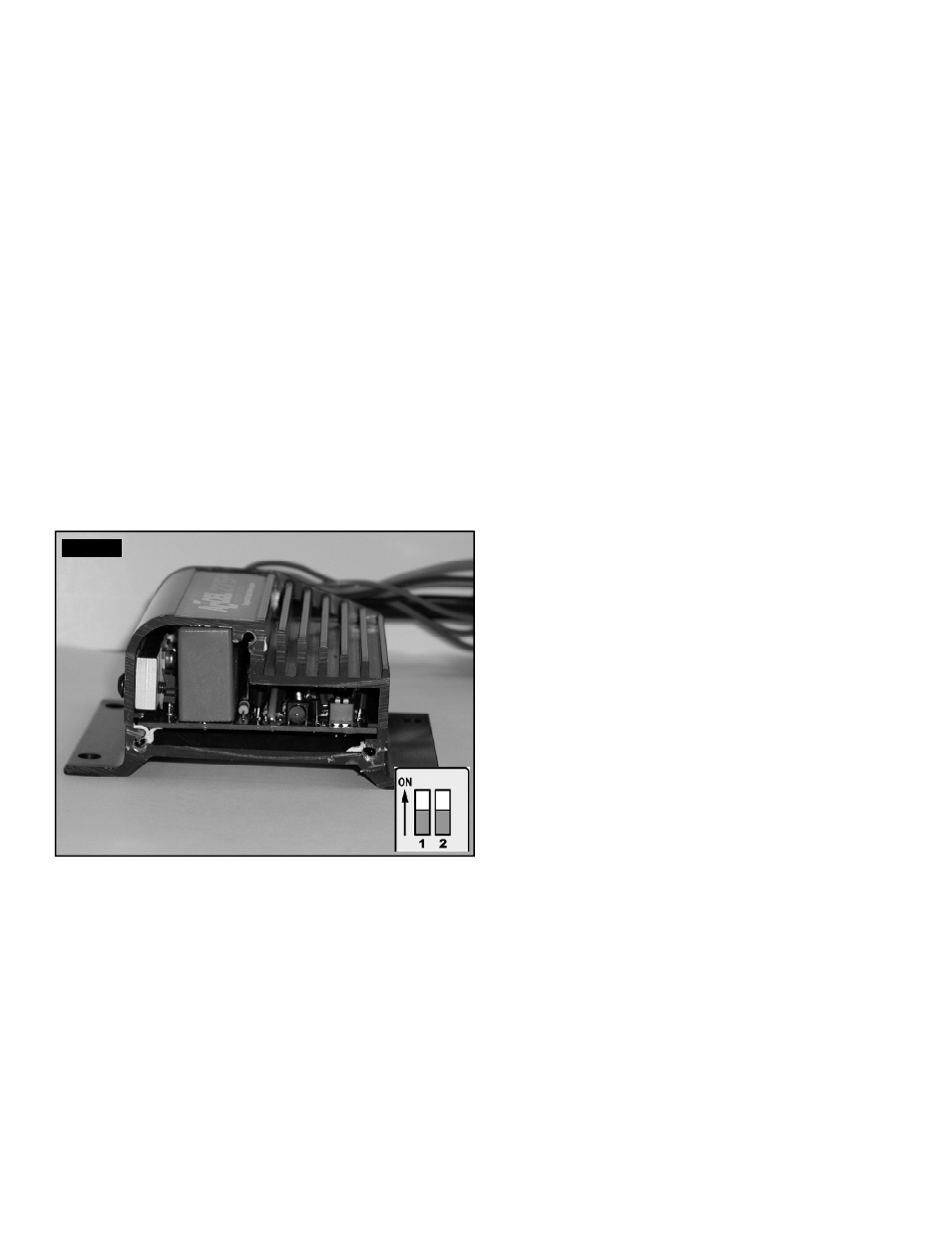
275+ Cylinder Selection Only
Your 275+ Ignition comes from the factory set up for
8 cylinder operation. If you want to use this ignition with a
4 or 6 cylinder engine, you must first remove the three
screws that hold the endplate opposite the wire harness end.
Once the endplate is removed, you’ll see the end of the
circuit board. Look for the two-section switch. To select 4
cylinder mode, move the switch marked "1" to the "ON"
position. To select 6 cylinder mode, move the switch marked
"2" to the "ON" position. If both switches are "OFF", or both
are "ON", the ignition will run in the 8 cylinder mode.
See Figure 1. For operation of the 300+ cylinder selection,
see page 4.
MOUNTING
The 275+ or 300+ Ignition Controls can be mounted in any
position. If you mount it in the engine compartment, keep it
away from moving objects and heat sources. The most
convenient method for mounting is with the wire harness
end down. This ensures easy access to the cylinder selection,
and on the 300+ the rev limiter selection switches. Do not
mount the unit in a closed area, such as the glovebox.
Also, do not mount the control box next to the distributor
or spark plug wire. This will eliminate any possibility of false
trigger signals.
When you find a suitable location to mount the unit, make
sure all wires of the ignition reach their connections. Hold
the ignition in place and mark the location of the mounting
holes. Mount the 275+ or 300+ using the mounting
hardware included in the kit.
WIRING
Wire Length
All of the wires of the 275+ or 300+ Ignition Controls may be
shortened as long as quality connectors are used or soldered
in place. To lengthen the wires, use one size larger gauge
wire (16 gauge). Use the proper connectors to terminate all
wires. All connections must be soldered and sealed.
Grounds
A poor ground connection can cause many frustrating
problems. When a wire is specified to go to ground, connect
it to the chassis or engine. Always connect a ground strap
between the engine and chassis. Connect any ground wires
to a clean, paint-free metal surface.
Ballast Resistor
Remove or bypass any ballast resistor or resistor lead if
so equipped.
WIRE FUNCTIONS
Trigger and Coil Leads
Red
Connects to a switched 12 volt source, such
as the ignition key.
Yellow
Connects to the positive (+) terminal of
the coil.
NOTE: This is the only wire that makes
electrical contact with the coil
positive (+) terminal.
Brown
Connects to the negative (–) terminal
of the coil.
NOTE: This is the only wire that makes
electrical contact with the coil
negative (-) terminal.
Trigger Wires
Either of two circuits will trigger the 275+
or 300+ Ignition Controls: a points or OE
trigger circuit (white wire) or a magnetic
pickup circuit (violet and orange wires).
NOTE: The two circuits will never be
used together.
White
Connects to points, electronic ignition
amplifier output or to the OE module
trigger circuit. When this wire is used, the
magnetic pickup connector is not used.
Violet/Orange Connect to factory magnetic pickups or
other aftermarket pickups. The orange wire
is positive (+) and the violet is negative (–).
When these wires are used, the white
wire is not used. Consult the chart that
shows the polarity of other common
magnetic pickups.
Green
Connects to an aftermarket tachometer.
ROUTING WIRES
Route all wires away from heat sources, sharp edges, and
moving objects. Route the trigger wires separate from the
other wires and spark plug wires and direct away from the
distributor. If possible, route them along a ground plane,
such as the block or firewall, which creates an electrical
shield. The magnetic pickup wires should be routed
separately and twisted together to help reduce extraneous
interference.
FIGURE 1
2