Ar – 1202, Architectural dimmer – Lightronics AR1202 User Manual
Page 8
Page
8
of
22
AR – 1202
RTC
ARCHITECTURAL DIMMER
Revision
1.93
OWNERS
MANUAL 06/03/2008
www.lightronics.com
Lightronics Inc.
509 Central Drive Virginia Beach, VA 23454
Tel 757 486 3588
SMART REMOTE CONNECTIONS
There are two types of smart remotes (push button and
fader) which can be used with the AR-1202. There are
multiple models of each type. They all connect to a
common RS-485 bus which is controlled by a AR-
1202. Additional AR-1202 dimmers may also be
connected on the same bus. One of them will be set as
the master controller by making
UNIT ADDRESS
ASSIGNMENTS
.
Smart remote signals to the AR-1202 are transmitted
over a two twisted pair, shielded, low capacitance
cable. One pair carries the RS-485 signal and the other
provides a low voltage power and common to the
remotes.
A smart remote bus should be daisy chained to all its
receiving units. It should NOT be connected in a star
arrangement with multiple "home runs".
Each smart remote has a 4 pin connector with screw
down terminals to connect to the RS-485 bus. You
must get the exact wiring pinout information for the
remote unit from its owners manual.
See the diagram "EXTERNAL CONNECTIONS" and
the example below for specific connection
information.
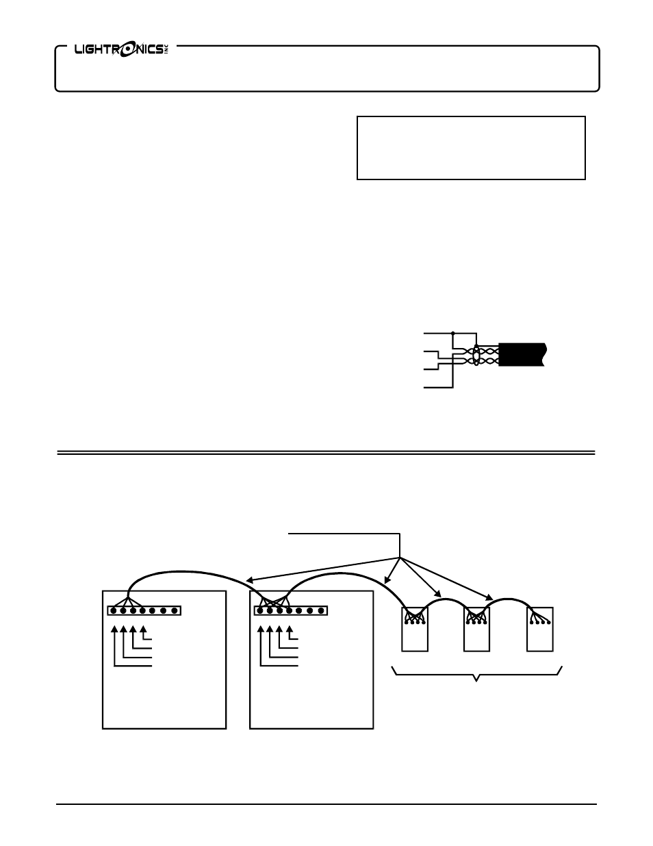
SMART REMOTE CONNECTIONS EXAMPLE
SMART
REMOTE
SMART
REMOTE
Dual Twisted Pair
Shielded Cable
Unit Address 00
Unit Address 01
AR-1202
AR-1202
1
2
3
4
5
6
7
1 2 3 4 5 6 7
Remote Voltage +
Remote Data +
Remote Data -
Remote Common
1 Remote Common (Pair 1)
2 Remote Data - (Pair 2)
3 Remote Data + (Pair 2)
4 Remote Voltage + (Pair 1)
Remote Voltage +
Remote Data +
Remote Data -
Remote Common
1 2 3 4
SMART
REMOTE
1
2
3
4
1 2 3 4
CAUTION
REMOVE ALL POWER FROM THE AR-1202
BEFORE MAKING OR CHANGING SMART
REMOTE CONNECTIONS.
Common
Voltage +
Data -
Data +
Shield
SMART REMOTES CABLE CONDUCTOR
ARRANGEMENT FOR DUAL TWISTED PAIR,
SHIELDED CABLE