Laurel Electronics LAUREATE SERIES Serial Comunications User Manual
Page 7
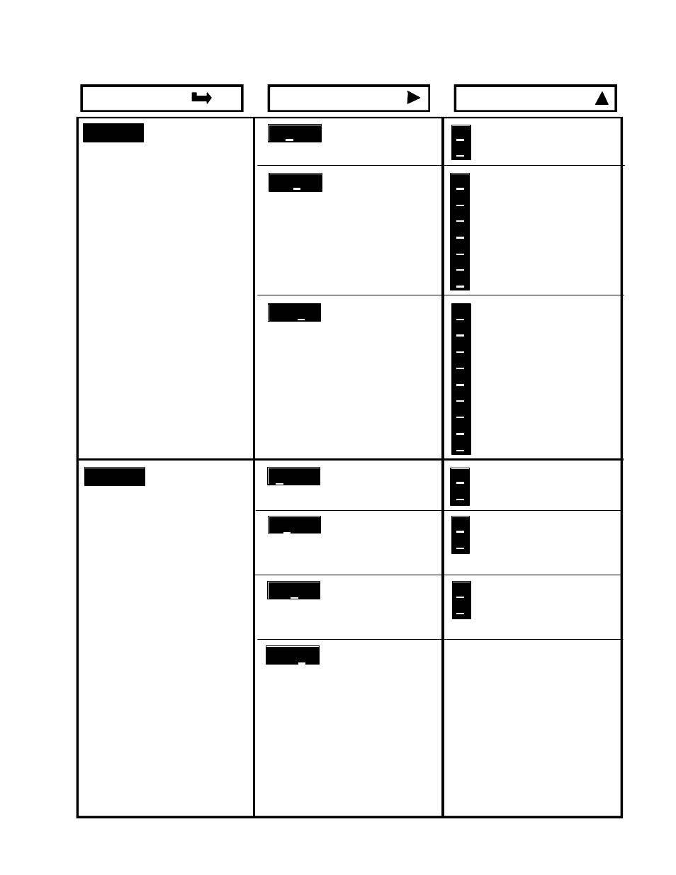
DIGIT SELECT KEY
VALUE SELECT KEY
MENU KEY
Ser 1
Serial interface setup
(only enabled if communica-
tions board installed)
Ser 2
Serial interface setup
(only enabled if communica-
tions board installed)
0
Send unfiltered signal
1
Send filtered signal
0
300 baud
1
600 baud
2
1200 baud
3
2400 baud
4
4800 baud
5
9600 baud
6
19200 baud
0
Output at reading rate
1
Output at rr/2
2
Output at rr/4
3
Output at rr/8
4
Output at rr/16
5
Output at rr/32
6
Output at rr/64
7
Output at rr/128
8
Output at rr/256
0
None after carriage rtn
1
LF after carriage return
0
No alarm data
1
Alarm data with reading
0
Continuous output
1
Output on RS-232 /
RS-485 command only
Addresses 1 thru 15 are de-
noted by 1 thru 9 and A thru F.
Addresses 16 thru 31 use the
same character followed by a
decimal point
000
Output filtering
000
Baud rate
000
Digital output rate
rr = reading rate (rate depen-
dent on gate time and input
frequency)
0000
Line Feed
0000
Alarm data transmitted with
meter readings
0000
Control of digital output
0000
Meter address for RS-232/
RS-485 communication
1.4
SERIAL INTERFACE SETUP - ALL METERS
-6-
- QLS Quad Output 4-20 mA Current Loop - Datasheet (3 pages)
- QLS Quad Output 4-20 mA Current Loop - Manual (8 pages)
- LTS6 - Datasheet (3 pages)
- LTS6 - Manual (24 pages)
- LT: 4-20 mA & Serial Data Output Transmitter for Duty Cycle Input (4 pages)
- LT SERIES TRANSMITTERS PULSE INPUTS (40 pages)
- LT: 4-20 mA & Serial Data Output Transmitter for Position or Rate from Quadrature Encoders (4 pages)
- LT: 4-20 mA & Serial Data Output Transmitter for Average Time of Periodic Events (4 pages)
- LT: 4-20 mA & Serial Data Output Transmitter for Time of Single or Accumulated Events (4 pages)
- LT: 4-20 mA & Serial Data Output Transmitter for AC Phase Angle & Power Factor (4 pages)
- LT: 4-20 mA & Serial Data Output Transmitter for Ratio (4 pages)
- LT: 4-20 mA & Serial Data Transmitter-Totalizer for 0-1 mA, 4-20 mA or 0-10V Process Signals (4 pages)
- LT: 4-20 mA & Serial Data Output Transmitter for Dual Channel Pulse Totalizer Input (4 pages)
- LT: Ethernet & 4-20 mA Output Transmitter for Frequency, Rate or Period Input (4 pages)
- LT SERIES TRANSMITTERS ANALOG INPUT (40 pages)
- LT: 4-20 mA Current Loop Transmitter for Resistance Input in Ohms (4 pages)
- LT: 4-20 mA & Serial Data Output Transmitter for Pt100, Cu10 and Ni120 RTD Input (4 pages)
- LT: 4-20 mA & Serial Data Output Transmitter for Thermocouple Types J, K, T, E, N, R, S (4 pages)
- LT: 4-20 mA & Serial Data Output Transmitter for Load Cell & Microvolt Signals (4 pages)
- LTE SERIES TRANSMITTERS ANALOG INPUT (40 pages)
- LTE: Ethernet & 4-20 mA Output Transmitter for Strain Gauge & Potentiometer Input (4 pages)
- LT: 4-20 mA & Serial Data Output Transmitter for Process Signals (4 pages)
- LT: 4-20 mA & Serial Data Output Transmitter for AC RMS Voltage or Current Input (4 pages)
- LT: 4-20 mA & Serial Data Output Transmitter for DC Voltage or Current Signals (4 pages)
- LTE SERIES TRANSMITTERS PULSE INPUT (40 pages)
- LTE: Ethernet & 4-20 mA Output Transmitter for Duty Cycle Input (4 pages)
- LTE: Ethernet & 4-20 mA Output Transmitter for Position or Rate from Quadrature Encoders (4 pages)
- LTE: Ethernet & 4-20 mA Output Transmitter for Average Time of Periodic Events (5 pages)
- LTE: Ethernet & 4-20 mA Output Transmitter for Time of Single or Accumulated Events (4 pages)
- LTE: Ethernet & 4-20 mA Output Transmitter for AC Phase Angle & Power Factor (4 pages)
- LTE: Ethernet & 4-20 mA Output Transmitter for Ratio (5 pages)
- LTE: Ethernet & 4-20 mA Output Transmitter & Totalizer for 0-1 mA, 4-20 mA or 0-10V Signals (4 pages)
- LTE: Ethernet & 4-20 mA Output Transmitter for Dual Channel Pulse Totalizer Input (4 pages)
- LTE: Ethernet & 4-20 mA Output Transmitter for Frequency, Rate or Period Input (4 pages)
- LTE: Ethernet & 4-20 mA Output Transmitter for Resistance in Ohms (4 pages)
- LTE: Ethernet & 4-20 mA Output RTD Transmitter for Pt100, Cu10 and Ni120 RTD Input (4 pages)
- LTE: Ethernet & 4-20 mA Output Transmitter for Thermocouple Types J, K, T, E, N, R, S (4 pages)
- LTE: Ethernet & 4-20 mA Transmitter for Load Cell & Microvolt Signals (4 pages)
- LTE: Ethernet & 4-20 mA Output Transmitter for Process Signals (4 pages)
- LTE: Ethernet & 4-20 mA Output Transmitter for AC RMS Voltage or Current (4 pages)
- LTE: Ethernet & 4-20 mA Output Transmitter for DC Voltage or Current (4 pages)
- LTSE6 - Manual (25 pages)
- LTSE6 - Datasheet (3 pages)
- MAGNA Series Large Digit Displays (4 pages)
- M-35 Microminature Process Meter (2 pages)