A9 a5 – Impulse 3405 User Manual
Page 6
Card
Setup
Sealevel Systems VERSA COMM+4/EX Page
3
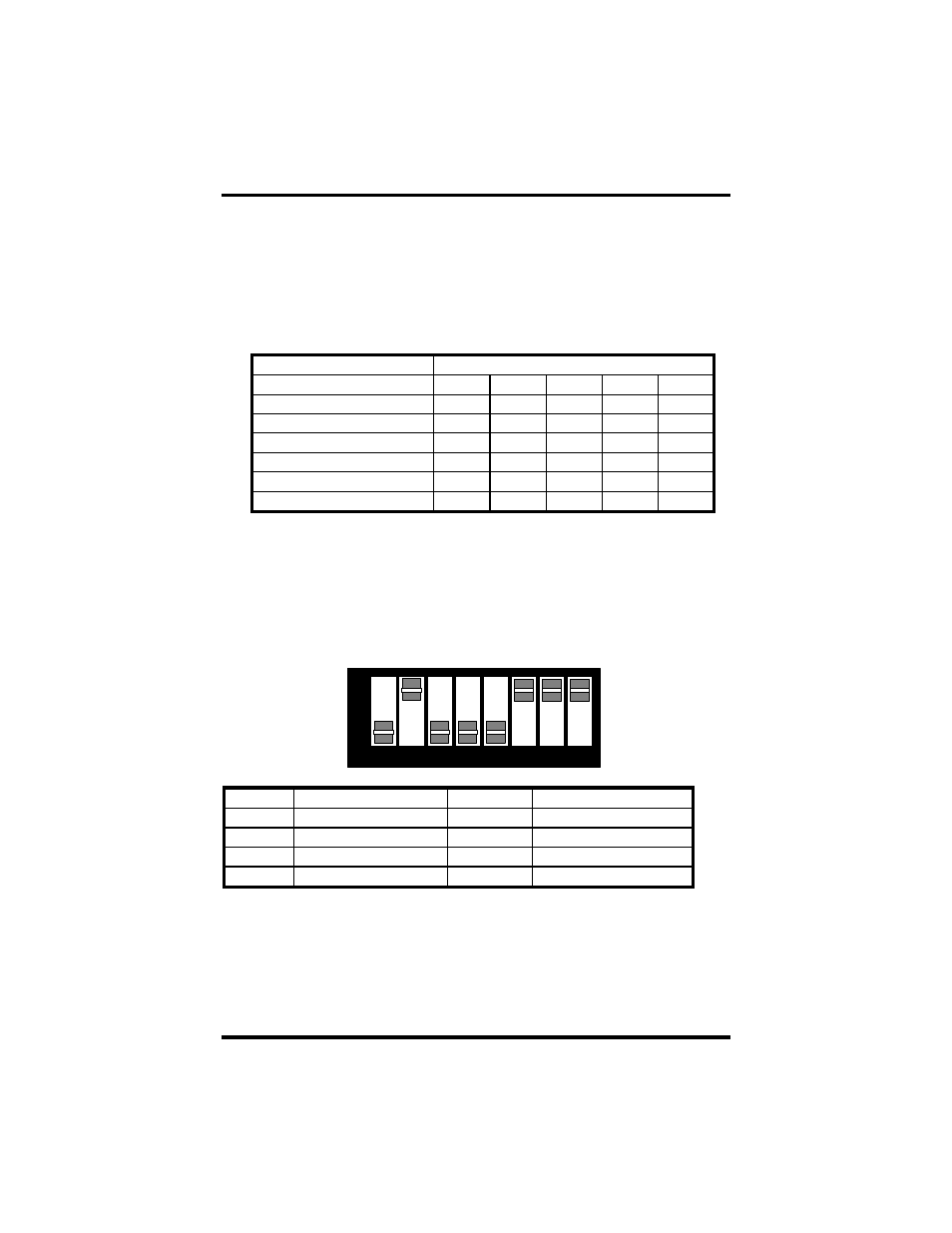
The second mode of address selection provides the compatibility mode. In this
mode the DIP-switch sets the base address and the adapter occupies 32
consecutive I/O locations. The following table illustrates the location of each
port and its relationship to the other ports.
Note: For switches 1 - 5 to become active, switches 6, 7 & 8 must be set in
the
‘On’ or ‘Up’ position.
Switch
Settings
Address lines
Æ
A9 A8 A7 A6 A5
Address
Selected 1 2 3 4 5
280-29F
Off On Off On On
2A0-2BF
Off On Off On Off
380-39F
Off Off Off On On
1A0-1BF
On Off Off On Off
2E0-2FF
Off On Off Off Off
Figure 2 - Address Selection Table
The following illustration shows the correlation between the DIP-switch setting
and the address bits used to determine the base address. In the example below,
address 2E0 is selected as a base. Address 2E0 in binary is XX 10 111X XXXX
where X = a non-selectable address bit.
Port #
Connector Location
Address
Example (Base=2E0)
1
1 Base+0
2E0-2E7
2
2 Base+8
2E8-2EF
3
3 Base+16
2F0-2F7
4
4 Base+24
2F8-2FF
Figure 3 - Port to Connector Table
1
2
3
4
5
6
7
8
ON
OFF
A9
A5