Hardware configuration, 8227 – jumper and dipswitch settings, Umper and – Impulse 8224 User Manual
Page 31: Ipswitch, Ettings
Hardware Configuration
8227 – Jumper and Dipswitch Settings
The SeaDAC 8227 module ships factory configured with the D/A outputs set for 0-
10V and current loop mode on the A/D inputs disabled. If you need to enable current
loop mode or set the D/A outputs to 0-5V, you will need to open the enclosure and
access the jumpers (shown on the next page).
NOTE:
Do not perform these instructions with USB or field wires
connected. Be sure to follow proper ESD procedures by grounding
yourself and the SeaDAC module.
What you will need:
SeaDAC 8227 module
Phillips head screwdriver
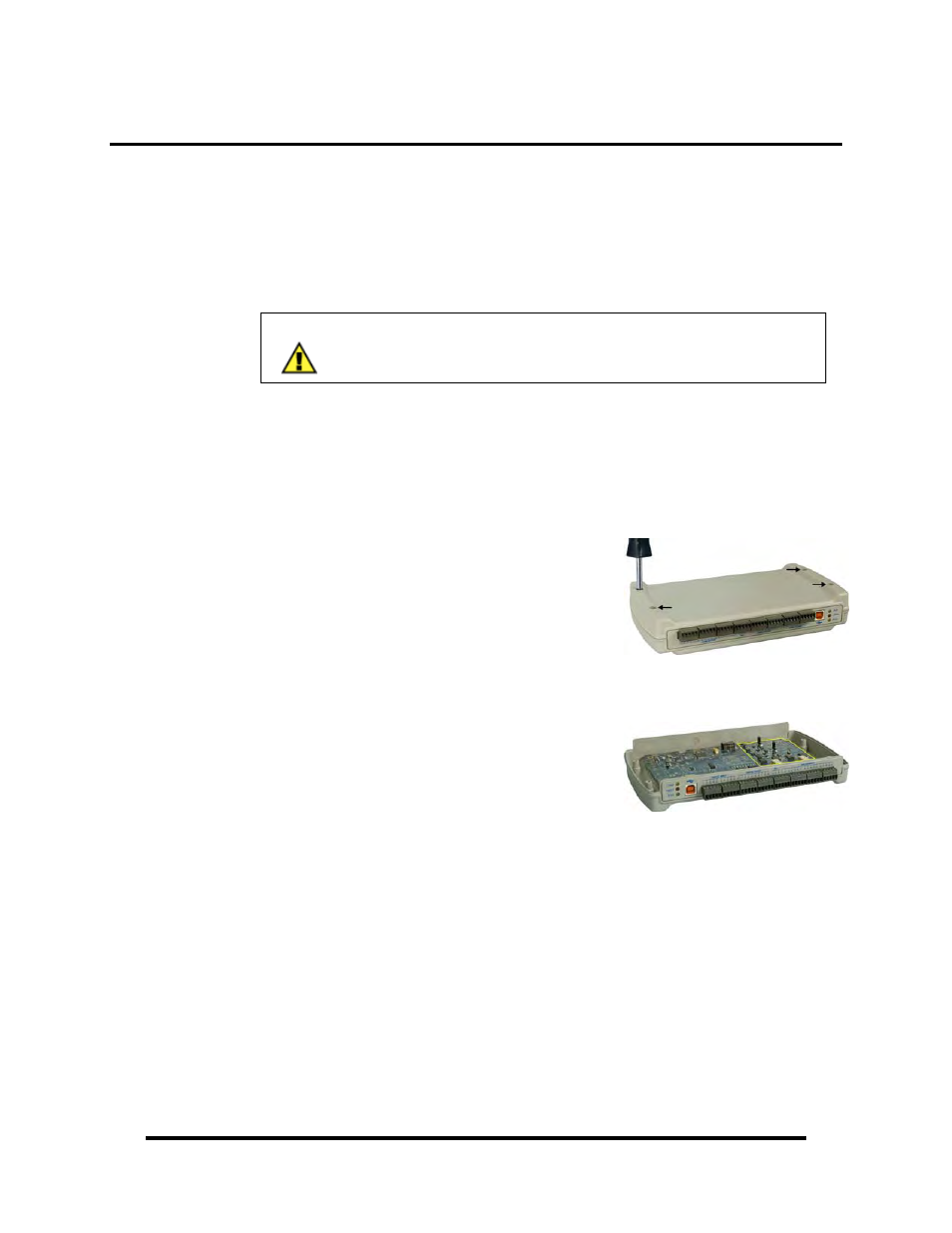
Step 1
Turn the SeaDAC 8227 module upside down and
remove the four black screws from the locations
shown in the image.
Step 2
Holding the top and bottom halves of the SeaDAC
module together, flip the module back over.
Remove the top half of the enclosure and set to the
side.
Jumpers and dipswitch locations are outlined in
the image to the right and are shown in detail on
the following page.
© Sealevel Systems, Inc.
- 29 -
SeaDAC User Manual