Card setup – Impulse ACB-104.ULTRA (3514) User Manual
Page 5
© Sealevel Systems, Inc.
- 3 -
ACB-104.ULTRA User Manual
Card Setup
Address Selection
As part of the PC/104-Plus specification, a means of selecting the appropriate signals
to identify the position in which the adapter is installed in the stack must be provided.
This is typically done via Dual 4:1 Mux/Demux chips and a rotary switch. They
provide a 5 ohm switch that connects the input and output together. These switches
provide a bi-directional path with no signal propagation delay other than the RC
delay of the on resistance of the switch and the load capacitance. This is typically
250ps at 50pF Load. Other methods of configuring the modules are possible, but the
rotary switch is the most convenient, cleanest and provides for the least possible error
in configuration. The clocks are tuned on the Host Board such that the length of
CLK3 trace is
.0.662" less than CLK2, CLK2 trace is .0.662" less than CLK1, and
CLK1 trace is
.0.662" less than CLK0. Therefore, the first module on the stack must
select CLK0 (the longest trace), the second CLK1, etc. This provides basically no
clock skew between modules. The table below shows the appropriate switch setting
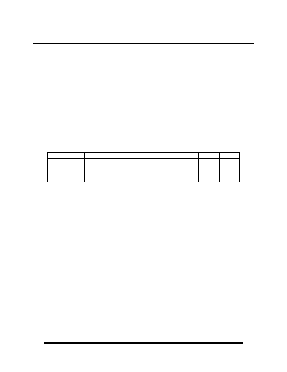
and signals used for each module in the stack.
Switch Position
Module Slot
CLKID
Address
INT0*
INT1*
INT2*
INT3*
0 or 4
1
CLK0
AD20
INTA*
INTB*
INTC*
INTD*
1 or 5
2
CLK1
AD21
INTB*
INTC*
INTD*
INTA*
2 or 6
3
CLK2
AD22
INTC*
INTD*
INTA*
INTB*
3 or 7
4
CLK3
AD23
INTD*
INTA*
INTB*
INTC*