E8 e9 e8 e9 – Impulse ACB-104 (3512) User Manual
Page 6
Card Setup
Sealevel Systems ACB-104 Page
3
Transmit Clock Header E5
Header E5 sets the input/output clock modes for the transmit clock (TXC). If the transmit clock is to be an input,
place the jumper to cover both pins. This board does not support transmit clock as an output.
RS-485 Mode Enable Header E4
E4 position ‘TE’ determines whether the RS-485 transmit driver is enabled by the Enhanced Serial
Communications Controller (ESCC) signal Request To Send (RTS) or always enabled. With the jumper installed,
RTS enables the driver. Removing the jumper enables the driver regardless of RTS. This jumper should only be
installed if you are running the board in a multi-drop polled environment such as RS-485, and you have software
that knows how to ‘talk’ on the RS-485 bus. For normal point-to-point RS-530 and RS-422, remove this jumper.
E4 position ‘ED’ is used to control the RS-485 enable/disable functions for the receiver circuit and determine the
state of the RS-422/485 driver. The RS-485 ‘Echo’ is the result of connecting the receiver inputs to the transmitter
outputs. Every time a character is transmitted; it is also received. This can be beneficial if the software can handle
echoing (i.e. using received characters to throttle the transmitter) or it can confuse the system if the software does
not. To select the ‘No Echo’ mode select silk-screen position ‘ED’.
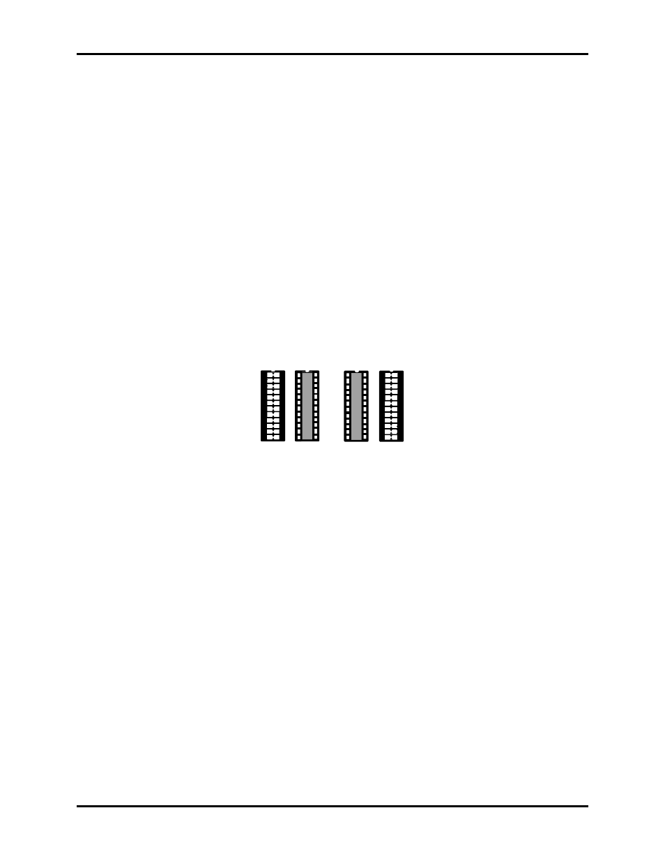
Electrical Interface Selection Headers E8 &E9
The ACB-104 has the ability to be used in either RS-232 or RS-530/422/485. This is selectable via two 24 pin DIP-
shunts at E8 & E9. Please use the following illustration to aid in the configuration of your electrical interface.
RS-422
RS-232
RS-422
RS-232
E8
E9
E8
E9
RS-422
RS-232
Figure 3 Headers E8 & E9, Electrical Interface Selection