Appendix f - silk-screen – Impulse ACB-104 (3512) User Manual
Page 21
Appendix E - Asynchronous and Synchronous Communications
Sealevel Systems ACB-104 Page
18
Synchronous Communications
Synchronous Communications is used for applications that require higher data rates and greater error checking
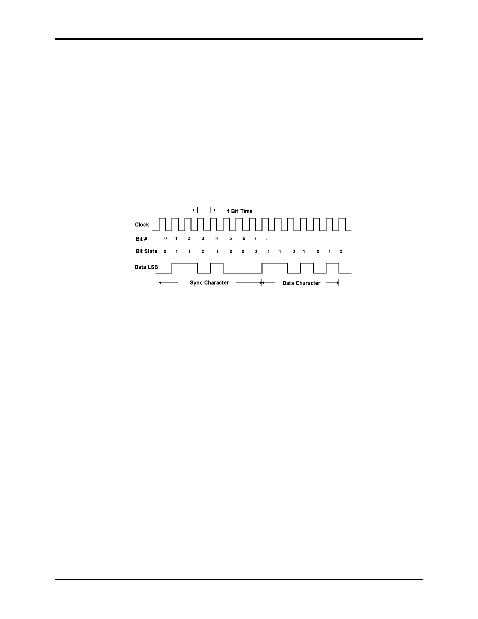
procedures. Character synchronization and bit duration are handled differently than asynchronous communications.
Bit duration in synchronous communications is not necessarily pre-defined at both the transmitting and receiving
ends. Typically, in addition to the data signal, a clock signal is provided. This clock signal will mark the beginning
of a bit cell on a pre-defined transmission. The source of the clock is predetermined and sometimes multiple clock
signals are available. For example, if two nodes want to establish synchronous communications, point A could
supply a clock to point B that would define all bit boundaries that A transmitted to B. Point B could also supply a
clock to point A that would correspond to the data that A received from B. This example demonstrates how
communications could take place between two nodes at completely different data rates. Character synchronization
with synchronous communications is also very different than the asynchronous method of using start and stop bits
to define the beginning and end of a character. When using synchronous communications a pre-defined character or
sequence of characters is used to let the receiving end know when to start character assembly.
Figure 9 - Synchronous Communications Bit Diagram
This pre-defined character is called a sync character or sync flag. Once the sync flag is received, the
communications device will start character assembly. Sync characters are typically transmitted while the
communications line is idle or immediately before a block of information is transmitted. To illustrate with an
example, let's assume that we are communicating using eight bits per character. Point A is receiving a clock from
point B and sampling the receive data pin on every upward clock transition. Once point A receives the pre-defined
bit pattern (sync flag), the next eight bits are assembled into a valid character. The following eight bits are also
assembled into a character. This will repeat until another pre-defined sequence of bits is received (either another
sync flag or a bit combination that signals the end of the text, e.g., EOT). The actual sync flag and protocol varies
depending on the sync format (SDLC, BISYNC, etc.).
For a detailed explanation of serial communications, please refer to the book Technical Aspects of Data
Communications by John E. McNamara, published by Digital Press (DEC) 1982.