Technical description – Impulse ACB-104 (3512) User Manual
Page 11
Technical Description
Sealevel Systems ACB-104 Page
8
Technical Description
The ACB-104 utilizes the Zilog 85230 Enhanced Serial Communications Controller (ESCC). This chip features
programmable baud rate, data format and interrupt control, as well as DMA control. Refer to the ESCC Users
Manual for details on programming the 85230 ESCC chip.
Features
• One channel of sync/async communications using 85230 chip
• DMA supports data rate greater than 1 million bits per second (bps)
• Selectable Port Address, IRQ level ( 3, 4, 5, 7, 9, 10, 11, 12, 15)
• Selectable DMA channels (0, 1, 2, 3)
• EIA-232 interface with full modem control signals TD, RD, RTS, CTS, DSR, DCD, DTR, TXC, RXC, TSET
signals
• EIA-530 interface with modem control signals TD, RD, RTS, CTS, DTR, TXC, RXC, TSET signals
• Jumper options for Transmit clock as input or output
• Software programmable baud rate
Internal Baud Rate Generator
The baud rate of the ESCC is programmed under software control. The standard oscillator supplied with the board is
7.3728 MHz. However, other oscillator values can be substituted to achieve different baud rates.
Programming the ACB-104
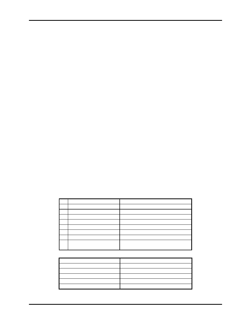
Control/Status Port
The ACB-104 occupies eight input/output (I/O) addresses. The ESCC chip uses the first four, while the fifth
address (Base+4) is the address of the on-board Control/Status Port. This port is used to set the Data Terminal
Ready (DTR) and to enable or disable DMA under program control, and to monitor the Data Set Ready (DSR)
input signals from the modem.
Bit
Output Port Bits
Input Port Bits
0
DTR A 1=On, 0=Off
DSR A 1=Off, 0=On
1
Unused bit
Unused bit
2
Unused bit
Unused bit
3
Unused bit
ESCC INT 1=Off, 0=On
4
Unused bit
Unused bit
5
Unused bit
TC STAT 1=Off, 0=On
6
Unused bit
Unused bit
7
CH. A DMA Enable
ESCC CH.A 1=On, 0=Off
Ch.A DMA 1=Off, 0=On
Software Examples
Function Program
Bits
Turn On CH.A DTR
Out (Base+4), XXXX XXX1
Turn Off CH.A DTR
Out (Base+4), XXXX XXX0
Enable DMA Drivers
Out (Base+4), 1XXX XXXX
Disable DMA Drivers
Out (Base+4), 0XXX XXXX
Test CH.A DSR
In (Base+4), Mask=0000 0001