Scmpb05, Position analog i/o backpanel, non-multiplexed, Scm5b – Impulse SCMPB01 User Manual
Page 9
For information call 800-444-7644
54
Isolated Analog Signal Conditioning Products
SCM5B
SCMPB05
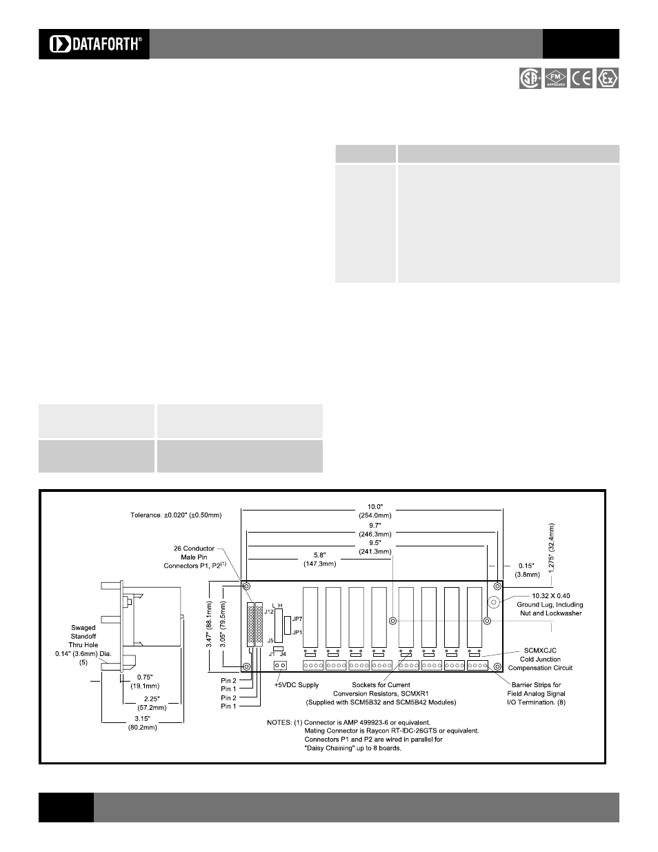
8-Position Analog I/O Backpanel, Non-Multiplexed
Description
The SCMPB05 backpanel (Figure 12) can accept up to eight SCM5B analog
input and/or output modules in any combination. It can be mounted on the
SCMXRK-002 19-inch metal rack. A separate analog signal path is provided
for each channel and each channels signal is accessible at redundant
26-pin connectors. The module output switch is continuously on when using
this backpanel and all eight module outputs are simultaneously accessible to
high-speed data acquistion (ADC) boards.
On-board jumpers permit paralleling two SCMPB05 boards to form a SCMPB01
equivalent. An additional set of inter-channel bridge jumpers permits connecting
an input modules output to an output modules input, providing two levels of
isolation (Figures 12, 13).
Jumpers on the SCMPB05 permit user selection of low (i.e. channels 0-7) or
high (i.e. channels 8-15) addresses.
A temperature sensor is mounted on each channel to provide cold junction
compensation for thermocouple input modules (See Figure 13 for
Schematic ). Field connections are terminated with four screw terminals at each
module site. Use system interface cable SCMXCA004-XX for connection to the
host system.
Ordering Information
Part Number Description
SCMPB05
Standard 8-channel backpanel.
SCMPB05-1
SCMPB05 without cold junction compensation circuits. Use
when cost savings is desired and thermocouple input
modules SCM5B37 and SCM5B47 will not be used.
SCMPB05-2
SCMPB05 with DIN rail mounting option. The backpanel is
mounted on a piece of anodized aluminum, which is
captured by the SCMXBEFE DIN rail mounting elements.
The backpanel is shipped fully assembled.
SCMPB05-3
SCMPB05-1 with DIN rail mounting option. See SCMPB05
and SCMPB05-2 for details.
Figure 12: SCMPB05 Analog I/O Backpanel
Specifications
Operating Temperature
40°C to +85°C
ATEX Group II, Category 3
20°C to +40°C
Relative Humidity
95% non-condensing
Interface Connector:
Field
high density screw clamp, 14 AWG max
System
26-pin, male header connector
Electrical
Address Selection
Module addresses may be selected as low (channels 0-7) or high (channels
8-15) using the sets of 3 pins labeled J5 through J12. Place a jumper over the
two pins closest to the ribbon cable connectors, P1 and P2, to select a low
address (factory configuration) or over the two pins furthest from the ribbon cable
connectors, P1 and P2, to select a high address.
Adjacent Channel Jumper
Adjacent channels may be connected together to provide an isolated output
signal from an isolated input module, providing two levels of 1500V isolation. This
capability is provided with the seven jumpers labeled JP1JP7. See page 48
for an example.
Refer to page 48 for additional notes on the P1 and P2 connectors, power
requirements, fusing and grounding issues.