Iii reset, Vfuse (automatic recovery), Vi pin connections – Controlled Products Systems Group K24M User Manual
Page 2: Vii warnings
2
3
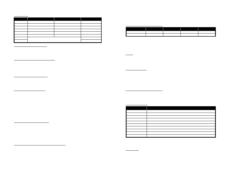
DIP Switches
Switch
On
Off
Factory Default
1
Presence Mode
Pulse Mode
Off
2
Exit Pulse
Entry Pulse
Off
3
FAULT Output
No FAULT Output
Off
4
2 Second Delay
No Delay
Off
5
Sensitivity Boost
No Boost
Off
6
Limited Presence
True Presence
Off
7
See table under Frequency section
On
8
Off
Presence/Pulse (DIP Switch 1)
Relay B has 2 modes of operation: Presence and Pulse. When in Pulse mode (DIP
switch 1 set to OFF), the 250 ms pulse can be set for entry pulse or exit pulse via DIP
switch 2. When in Presence mode, the presence hold time is the same as Output A.
Entry Pulse/Exit Pulse (DIP switch 2)
In Pulse Mode (with DIP switch 1 set to OFF), the detector can be programmed to
output a 250 millisecond pulse only upon vehicle entry over the loop or only upon
vehicle exit from the loop. DIP switch 2 has no effect on output A (the presence
output).
FAULT Output (DIP switch 3)
Setting DIP Switch 3 to OFF enables the settings programmed via DIP switches 1 and
2 for Relay B. Setting the DIP switch to ON disables DIP switches 1 and 2 and forces
an output on Relay B on a loop failure. Factory default for DIP switch 3 is OFF.
Output Delay (DIP Switch 4)
A 2 second delay of outputs A and B can be activated by setting DIP switch 4 to the
ON position. Output delay is the time the detector output is delayed after a vehicle
first enters the loop detection area. If the 2 second Output Delay feature is activated,
the output relays will only be turned on after 2 seconds has passed with a vehicle
continuously present in the loop detection area. If a vehicle leaves the loop detection
area during the 2 second delay interval, detection is aborted and the next vehicle to
enter the loop detection area will initiate a new full 2 second delay interval. By
flashing the front panel DET LED at 4 Hz with a 50% duty cycle, the detector
indicates that a vehicle is being detected but that the output is being delayed.
Sensitivity Boost (DIP Switch 5)
DIP switch 5 can be turned ON to increase sensitivity only during the detect period
without changing the sensitivity of a vacant loop. When a vehicle enters the loop, the
detector will automatically boost the loop sensitivity during the detect condition. As
soon as no vehicle is detected, the detector immediately returns to the original
sensitivity level. This feature helps prevent dropouts during the passage of high-bed
vehicles and is particularly useful in sliding gate situations.
Limited Presence/True Presence (DIP switch 6)
Output A always a presence output. The detector has two presence hold time modes:
Limited Presence and True Presence. When set for True Presence (DIP switch 6
OFF), the detector will hold the output call for as long as a vehicle is present in the
loop detection area and power is not removed or reset applied. True Presence time
applies only for normal size automobiles and trucks and for normal size loops (loop
area approx. 12 ft
2
to 120 ft
2
). When set for Limited Presence (DIP switch 6 ON), the
detector will typically hold the Call for about one to three hours when a vehicle is in
the detection zone.
Frequency (DIP switches 7 and 8)
Switch
Low
Normal
Medium
High
7
On
On
Off
Off
8
On
Off
On
Off
Loop frequency is controlled by DIP switches 7 and 8. Sometimes where loops are in
close proximity, it is necessary to select a different frequency for each loop to avoid
loop interference – commonly known as crosstalk. Four frequencies are available as
shown in the above table. Normal is the default frequency.
III Reset
Changing any DIP switch position (except 7 or 8) will reset the detector. After
changing the frequency selection switches, the detector will require a reset (a reset
will clear the loop fault memory).
IV CALL Memory
When power is removed for 2 seconds or less, the detector automatically “remembers”
if a vehicle was present and a CALL was in effect. When power is restored, the
detector will continue to output a CALL until the vehicle leaves the loop. Power loss
or dips of 2 seconds or less will not bring a gate arm down onto cars as they wait at
the gate.
V
Fuse (Automatic Recovery)
If 120VAC power is applied to the Model K-24, the automatic fuse will open. The
fuse will automatically reset when power is removed for three seconds. Check source
voltage before reinstalling.
VI Pin Connections
Pin
Function
1
Relay B, Common
2
Relay B, Normally Open (N.O.)
3
Relay B, Normally Closed (N.C.)
4
Relay A, Common
5
Relay A Normally Closed (N.C.)
6
Relay A, Normally Open (N.O.)
7
Power (Neutral)
8
Power (Hot)
9
Loop
10
Loop
Note: All relay contacts shown above are with power applied, loops connected, and
no vehicle present. Output B always operates in Fail Secure mode when loop or
power fails.
VII Warnings
Separately for each loop, the lead-in should be a twisted pair created by twisting two
(2) loop wires all the way from the loop to the detector (including through all wiring
harnesses) at approximately six (6) full twists per foot. For trouble free operation, it is
highly recommended that all connections (including crimped connectors) be soldered.