Dsp-10 instructions and specifications – Controlled Products Systems Group DSP-10LV User Manual
Page 2
DSP-10 INSTRUCTIONS AND SPECIFICATIONS
Delay - With DIPSWITCH 1 turned off there is no delay. With DIPSWITCH 1
turned on there is a 2 second delay before output A occurs. This 2 second
delay is “flashed” on the CALL LED. If the vehicle leaves before the two
seconds has timed out, the output will not occur. Delay only affects Output
A.
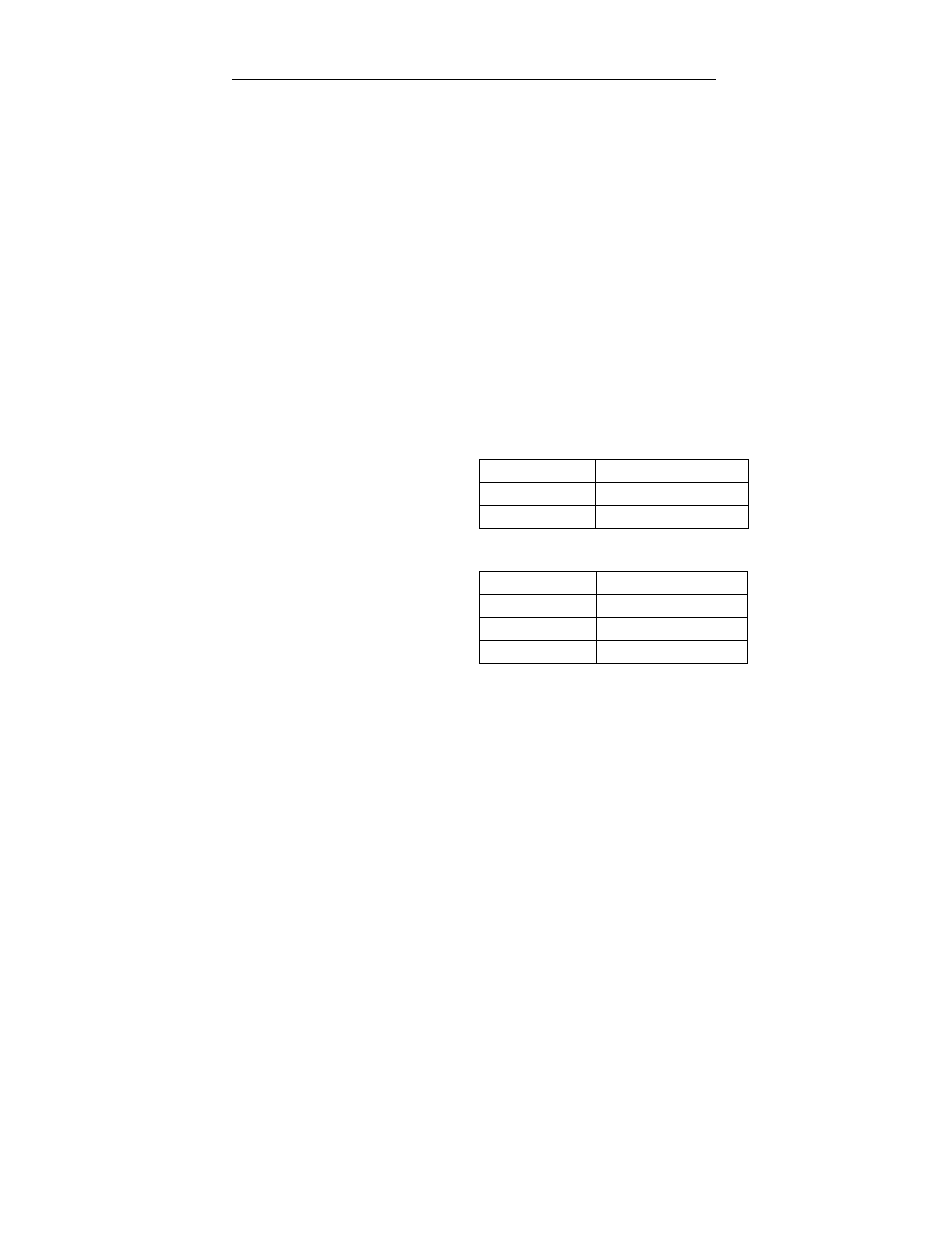
Extension - DIPSWITCHES 2 and 3 are used to select extension timing.
See chart below for extension times. Extension allows a vehicle to be
“remembered” for a period of time after the vehicle has left the loop.
Selected extension time is flashed on the call LED. Extension timing only
affects Output A.
DIP Switch 2
DIP Switch 3
0 seconds
Off
Off
2 seconds
On
Off
5 seconds
Off
On
10 seconds
On
On
Sensitivity Boost - DIPSWITCH 4 selects this feature. With switch 4 turned
on, sensitivity is automatically boosted during a call to improve detection of
high-bed vehicles and truck/trailer combinations. Sensitivity boost is not
applicable to most situations.
Output B Function Select - DIPSWITCHES 5 and 6 determine the function
of the second output relay, Output B. See chart below to select a specific
function. This output can be used in any one of the following ways:
True presence - The relay is energized whenever a vehicle is
present. The relay is not affected by any delay or extension timing.
Entry pulse - The relay is energized for 250 mS when a vehicle
enters the loop, or after the delay interval, if programmed.
Exit pulse - The relay is energized for 250 mS when a vehicle exits
the loop or after the extension time, if programmed.
Loop fail - If the inductive loop fails (opens or shorts), the output B
relay energizes.
DIP Switch 5
DIP Switch 6
True Presence
Off
Off
Entry Pulse
On
Off
Exit Pulse
Off
On
Loop Fail
On
On
Presence - DIPSWITCH 7 is normally left in the off position. If extended
presence is required, this switch is turned on. This feature is only used in
those rare cases when a vehicle will be over the loop for a long time (loading
dock, etc.).
Loop Failure Memory - With DIPSWITCH 8 turned on, the DSP-10 will
indicate a prior intermittent loop failure.
Frequency - One of four operating frequencies can be selected by using
front panel DIPSWITCHES 9 and 10
DIP Switch 9
DIP Switch 10
High
Off
Off
Medium High
On
Off
Medium Low
Off
On
Low
On
On
Fail Safe Operation (Factory Default) - In fail safe mode the output A relay
is energized and will de-energize for any one of the following conditions:
vehicle detection, loop failure, or power failure. In this mode, continuity will
occur between connector pins 5 and 10 whenever a vehicle is detected.
Fail Secure Operation - In fail secure mode the output A relay is de-
energized and will energize for either vehicle detection or loop failure. In this
mode, continuity will occur between connector pins 5 and 6 whenever a
vehicle is detected.
Sensitivity - Experience has shown that almost all parking and access
control applications can be handled with sensitivity set at NORMAL (level 5).
The rotary sensitivity switch is rarely moved from NORMAL. However, the
DSP-10 has ten sensitivity settings varying from LOW (level 0) to HIGH
(level 9).
NOTE - Changing any DIPSWITCH or ROTARY SWITCH setting
automatically resets the detector.
Indicators -
The green POWER LED shows the following status:
Normal
On
Loop open
Slow flash
Loop shorted
Fast flash
The red DETECT LED shows the following status:
Delay
Blinks slowly
Detect
On
Extension
Blinks fast
No Detect
Off
Output Relay Ratings - 3A, 150 VDC or 300 VAC.
Power - DSP-10-LV (10 to 30 Volts AC or DC), DSP-10-117 (117 Volts AC) ,
DSP-10-230 (230 Volts AC)
Power consumption less than 3 Watts (all models).
Enclosure - Impact resistant, high temperature plastic.
H - 2.375” (60mm) W - 1.75” (45mm) D - 3.61” (92mm)
Connector - Amphenol 11-pin connector:
1 (Black) - AC hot / DC +
2 (White) - AC neutral / DC COM
3 (Orange) - B relay (Closes for detect)
4 (Green) - Chassis ground
5 (Yellow) - A relay COM
6 (Blue) - A relay (Closes for detect)
7 (Gray) - Loop
8 (Brown) - Loop
9 (Red) - B relay Common
10 (Pink) or (White/Black) - A relay (Opens for detect)
11 (Violet) or (White/Red) - B relay (Opens for detect)
Operating Temperature - -35°F to 165°F (-37°C to 74°C)
Ordering Information - Standard parts numbers are as follows:
DSP-10-LV
10 to 30 Volts, AC or DC
DSP-10-117
117 Volts AC
DSP-10-230
230 Volts AC
Phone: (866) 395-6677 (Toll Free)
DSP10_CUT_U
Web Site: www.diablocontrols.com