Controlled Products Systems Group AX3 User Manual
Page 2
2
3
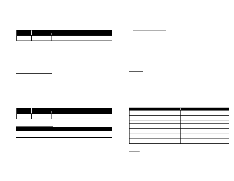
Frequency (DIP Switches 1 and 2):
In situations where loop geometry forces loops to be located in close proximity to one another, it
may be necessary to select different frequencies for each loop to avoid loop interference, commonly
known as crosstalk. DIP switches 1 and 2 can be used to configure the detector to operate at one of
four frequencies corresponding to Low, Medium / Low, Medium / High, and High as shown in the
table below.
NOTE: After changing any frequency switch setting(s), the detector must be reset by momentarily
changing one of the other switch positions or pressing the front panel RESET pushbutton.
Switch
Frequency
Low (0)
Medium / Low (1)
Medium / High (2)
High (3) *
1
ON
OFF
ON
OFF *
2
ON
ON
OFF
OFF *
* Factory default setting.
Presence / Pulse (DIP Switch 3):
The output relay has two modes of operation: Presence and Pulse. When set to operate in Presence
mode (DIP switch 3 OFF), an internal DIP switch can be used to select one of two presence hold
times; Limited Presence or True Presence
TM
. When set to operate in Pulse mode (DIP switch 3 ON),
the internal DIP switch can be used to configure the pulse output to occur when the vehicle enters
the loop detection zone (Pulse-on Entry) or when the vehicle leaves the loop detection zone (Pulse-
on-Exit). (See the Presence Hold Time or Output Relay Pulse Mode section below for details.)
The factory default setting is OFF (Presence Mode).
Sensitivity Boost (DIP Switch 4):
DIP switch 4 can be turned ON to increase sensitivity during the detect period without changing the
sensitivity during the no detect period. The boost feature has the effect of temporarily increasing the
sensitivity setting by up to two levels. When a vehicle enters the loop detection zone, the detector
automatically boosts the sensitivity level. As soon as no vehicle is detected, the detector
immediately returns to the original sensitivity level. This feature is particularly useful in preventing
dropouts during the passage of high bed vehicles. The factory default setting is OFF (no Sensitivity
Boost).
Sensitivity (DIP Switches 5 and 6):
DIP switches 5 and 6 select one of the four (4) sensitivity levels available as shown in the table
below. Use the lowest sensitivity setting that will consistently detect the smallest vehicle that must
be detected. Do not use a sensitivity level higher than necessary.
Switch
Sensitivity Level (-
ΔL/L)
0.32% (0)
0.16% (1) *
0.08% (2)
0.02% (3)
5
OFF
ON *
OFF
ON
6
OFF
OFF *
ON
ON
* Factory default setting.
iii. PC Board Mounted DIP Switches:
Switch
ON
OFF
Factory Default
1
Exit Pulse or Limited Presence
Entry Pulse or True Presence
TM
OFF
2
Two Second Delay
No Delay
OFF
Presence Hold Time or Output Relay Pulse Mode (DIP Switch 1):
When front panel mounted DIP switch 3 is set to PRES, one of two presence hold times can be
selected by means of DIP switch 1 on the two-position, PC board mounted DIP switch (labeled
SW2). Limited Presence and True Presence
TM
modes both provide a Call output when a vehicle
is present in the loop detection zone. When DIP switch 1 is ON, Limited Presence is
selected, and the detector will typically hold the Call outpu t for one to three hours. When
DIP switch 1 is OFF, True Presence
TM
mode is selected, and the detector will hold the Call
output as long as the vehicle is present in the loop detection zone and power is not removed.
True Presence
TM
time applies only for normal size automobiles and trucks and for normal
size loops (approximately 12 ft
2
to 120 ft
2
).
When front panel mounted DIP switch 3 is set to PULSE, one of two pulse output modes can be
selected by means of DIP switch 1 on the two-position, PC board mounted DIP switch (labeled
SW2). The Pulse-on-Entry setting (DIP switch 1 OFF) causes the output relay to provide a 250
millisecond pulse when a vehicle enters the loop detection zone. The Pulse-on-Exit setting (DIP
switch 1 ON) causes the output relay to provide a 250 millisecond pulse when a vehicle exits the
loop detection zone.
The factory default setting is OFF (Pulse-on-Entry / True Presence
TM
).
Output Delay (DIP Switch 2):
A two second delay of the output can be activated by setting DIP switch 1 to the ON position.
Output delay is the time the detector output is delayed after a vehicle first enters the loop detection
zone. If the two second Output Delay feature is activated, the output relay will only be turned on
after two seconds have passed with a vehicle continuously present in the loop detection zone. If the
vehicle leaves the loop detection zone during the two second delay interval, detection is aborted and
the next vehicle to enter the loop detection zone will initiate a new full two second delay interval.
The detector provides an indication that a vehicle is being detected but that the output is being
delayed, by flashing the front panel DET LED at a four Hz rate with a 50% duty cycle. The factory
default setting is OFF (no Output Delay).
III.
Reset:
Pushing the front panel RESET pushbutton or changing any DIP switch position (except 1 or 2) will
reset the detector. After changing the frequency selection switches, the detector must be reset.
IV.
Call Memory:
When power is removed for two seconds or less, the detector automatically remembers if a vehicle was
present and a Call was in effect. When power is restored, the detector will continue to output a Call until
the vehicle leaves the loop detection zone (loss of power or power dips of two seconds or less will not
bring a gate arm down onto cars as they wait at the gate).
V.
Failed Loop Diagnostics:
The FAIL LED indicates whether or not the loop is currently within tolerance. If the loop is out of
tolerance, the FAIL LED indicates whether the loop is shorted (one Hz flash rate) or open (steady ON).
If and when the loop returns to within tolerance, the FAIL LED will flash at a three flashes per second
rate to indicate that an intermittent loop fault has occurred and has been corrected. This flash rate will
continue until another loop fault occurs, the detector is reset, or power to the detector is interrupted.
VI.
Pin Connections (Reno A & E Wiring Harness Model 802-4):
Pin
Wire Color
Function
1
Black
AC Line / DC +
2
White
AC Neutral / DC Common
3
Orange
No Connection
4
Green
No Connection
5
Yellow
Relay, Common
6
Blue
Relay, Normally Open (N.O.)
7
Gray
Loop
8
Brown
Loop
9
Red
No Connection
10
Violet or
Black / White
Relay, Normally Closed (N.C.)
11
White / Green or
Red / White
No Connection
Note: All pin connections listed above are with power applied, loop(s) connected, and no vehicle detected.
VII. Warnings:
Separately, for each loop, a twisted pair should be created consisting of only two (2) loop wires running
the entire distance from the loop to the detector (including runs through all wiring harnesses) at a
minimum of six (6) complete twists per foot. For trouble free operation, it is highly recommended that
all connections (including crimped connectors) be soldered.