M30 assembly_pg1_revd, M30 plan site design, Clear opening – Controlled Products Systems Group STRONGARM M30 User Manual
Page 3: Secure side public side
© 2013
www.hysecurity.com
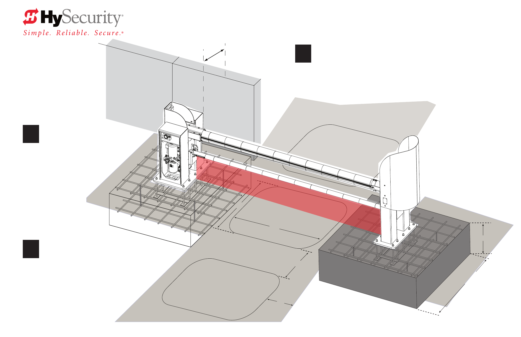
Minimum Clearance
for accessibility: 2 feet (61 cm)
Dimensions:
A = 6 to 16 feet (183 to 488 cm) B = 6 to 8 feet (183 to 244 cm)
C = Maintain 4 feet (122 cm) between loop & edge of roadway
D = Maximum distance is 5 feet (152 cm). Vehicle must move
from one loop to the next without loss of detection.
NOTE:
If tailgating is a concern, dimension “B” may be reduced to
3 ft (91 cm), but detecting high bed vehicles will be substantially impaired.
* Concrete Dimensions
6 x 6 x 2 foot (183 x 183 x 61 cm)
Optional: 4 x 4 x 4 foot square (122 x 122 x 122 cm)
Measure
the clear opening. Use the templates
provided to align conduit and determine placement
of the posts. Turn this page over to view Assemble and
Align and Mark instructions.
StrongArm M30 Installation & Assembly - Plan Site Design
Page 1
M30 PLAN SITE DESIGN
Read & Plan
Read and follow the Important Safety Information provided in the Programming and Operations
Manual prior to installing the StrongArm M30™ Crash Rated Fortified Barrier Arm. Review these
installation instructions and make sure to conform to site specifications and all local and federal
regulations and codes.
2
3
Design Vehicle Loops
If automatic close is desired, a RESET and one other loop
(IOLD or OOLD) is required.
Three loops are preferred: RESET, IOLD, OOLD (Free Exit, optional)
Reset Loop
Roadway
Secure Side
Public Side
B
A
Clear Opening
D0432 Rev D
Outside
Obstruction
Loop (OOLD)
Inside
Obstruction
Loop (IOLD)
6 ft*
(183 cm)
2 ft*
(61 cm)
D
C
1
Centered under Barrier
Arm