M30 assembly_pg8_revd, M30 complete the installation, I on – Controlled Products Systems Group STRONGARM M30 User Manual
Page 10
© 2013
www.hysecurity.com
Page 8
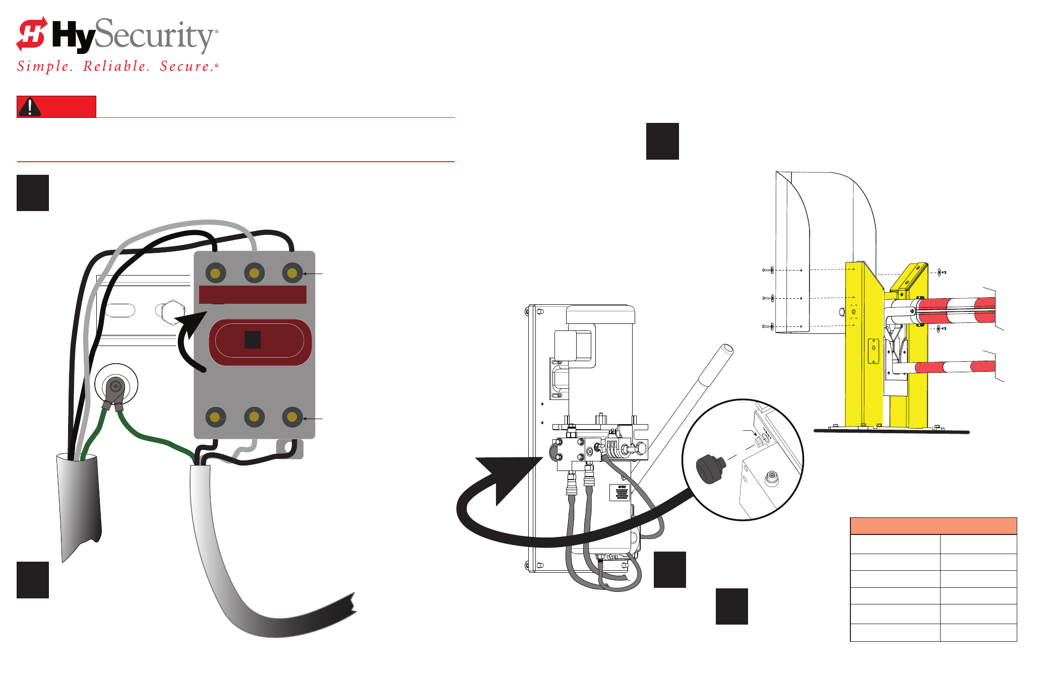
Turn OFF AC power at the source (circuit breaker panel) before accessing the wires in the StrongArm M30
junction box. Follow facility Lock Out/Tag Out procedures. Make sure all power switches are in the OFF
position. Follow all electrical code standards and regulations.
DANGER
Connect to Power:
Three wires and a ground are available for connection to a 3 Phase power source
(3Ø).
Loosen the screws on the power module to open the wire slots at the top and bottom.
1
Remove the Vent Plug.
I ON
I ON
ON
OFF
M30 COMPLETE THE INSTALLATION
2
StrongArm M30 Installation & Assembly - Complete the Installation
D0432 Rev D
NOTE: Wiring of gate operators must conform to NEC standards
and comply with all local codes. When the installation is compliant and
complete, turn on AC power at the source and power module.
Jacket to VFD wire connections
Disconnect Switch
3Ø supply power connection shown
NOTE: 1Ø optional: Omit wire (do not connect) to L2 wire if supply power is 1Ø.
Vent Plug
3
Install entrapment shield:
Remove the six hex head screws and fender washers
from the Catch posts and use them to secure the Entrapment Shield as shown.
Tighten all six screws using a 7/32 hex key.
4
Replace it with
the Breather Cap.
5
Breather Cap
Ground
Top screws: Loosen and
open wire slots.
Loosen screws and
open wire slots.
Directional power switch
Connect AC Power:
Place the incoming power wires
into their appropriate slots.
Attach the ground wires to the chassis.
Conduit
(Not to scale)
L1
L2
L3
T1
T3
T2
Torque Requirements:
Bolt size
(inches)
ft
∙
lbs N
∙
m
¼ - 20
10 13
⅜ – 16
28 28
½ - 13
75 102
⅝ – 11 & ⅝ – 18
150 203
¾ - 10
200 271