Section 1 - installation, 1 specifications – Controlled Products Systems Group 9150-080 User Manual
Page 15
SECTION 1 - INSTALLATION
Prior to beginning the installation of the slide gate operator, we suggest that you become familiar with
the instructions, illustrations, and wiring guide-lines in this manual. This will help insure that your
installation is performed in an efficient and professional manner.
The proper installation of the vehicular slide gate operator is an extremely important and integral part
of the overall access control system. Check all local building ordinances and building codes prior to
installing this operator. Be sure your installation is in compliance with local codes.
1.1 Specifications
Class of Operation:
Class I, II, III, IV
Type of Gate:
Vehicular Slide Gates Only
Horsepower:
1/2 and 1 H.P.
Voltage / Phase:
120 or 230 VAC single-phase; 230 or 460 VAC three phase.
Current:
Varies with motor, voltage and phase. See page 28.
Max Gate Weight:
½ HP – 1000 Lb., 1 HP - 1500 Lbs.
1, 2
Max Gate Length:
½ HP – 30 Ft., 1 HP - 45 Ft.
1
Cycles / Hr:
60/Hr
Speed:
Approximately 1 Ft./Sec.
Entrapment Protection:
Primary – Inherent (Type A)
Secondary – Provision for connection of a non-contact
sensor (Type B1) and/or a contact sensor (Type B2).
Secondary entrapment protection devices are not supplied
with the operator and must be ordered separately.
Note 1: Assumes gate is in good working condition installed
on a level surface.
Note 2: Operators with convenience open option
½ HP – 800 Lb., 1 HP - 1300 Lbs
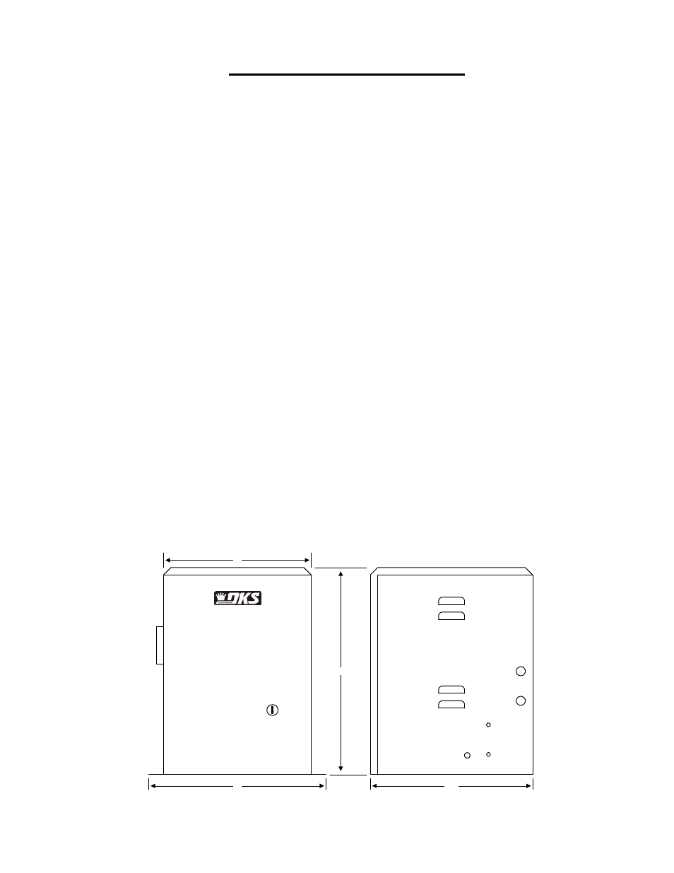
18
16.5
15
24
9150-065-D-5-07
Page
15
Figure 1