2 switch settings – Controlled Products Systems Group 9100-080 User Manual
Page 36
3.2 Switch
Settings
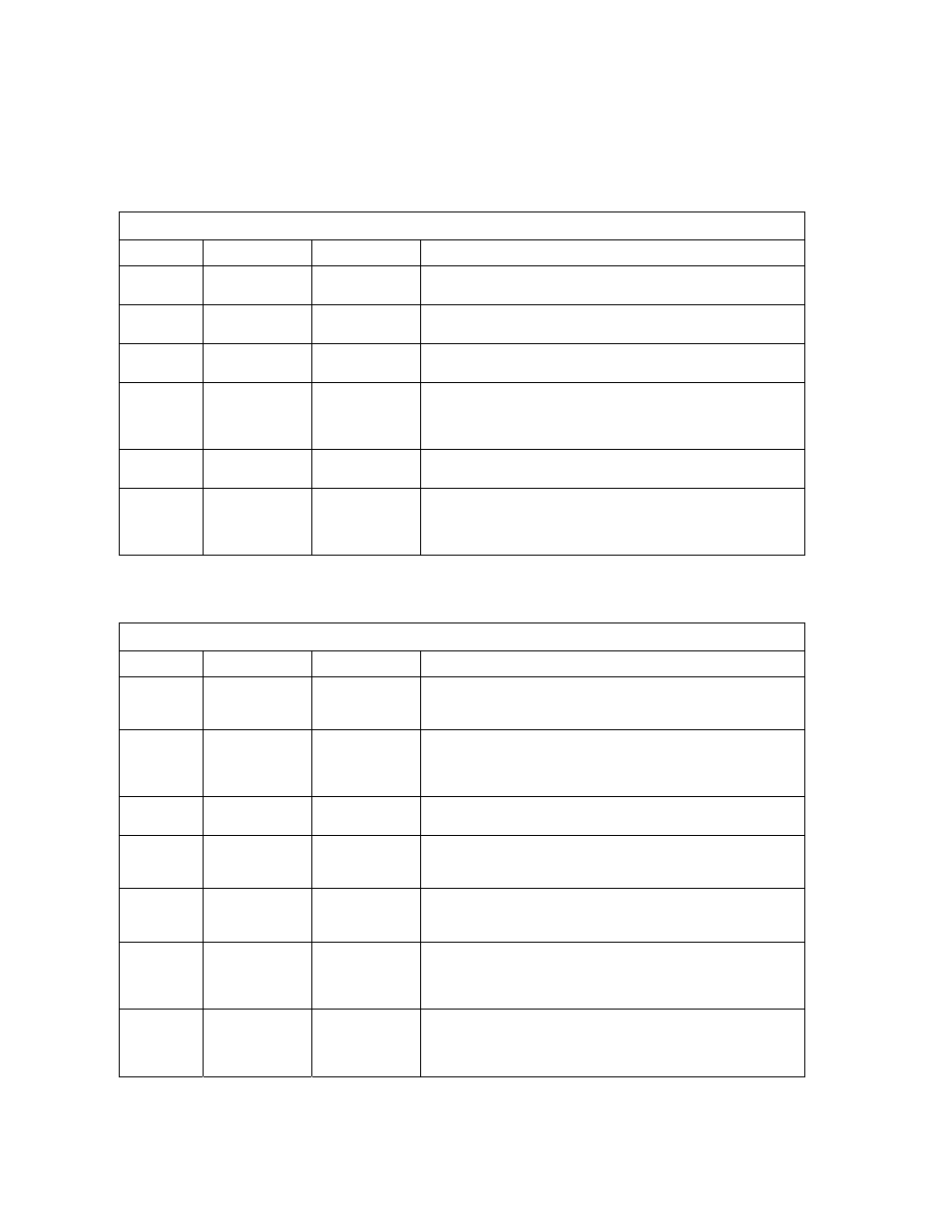
The two DIP-switches located on the circuit board are used to program the operator to operate in
various modes and to turn on or off various operating features. Whenever a switch setting is
changed, power to the operator must be turned OFF and then turned back on for the new setting to
take affect. Check and review ALL switch settings prior to applying power to the operator.
SW 1 (LEFT SWITCH)
SWITCH FUNCTION SETTING
DESCRIPTION
1 Direction
OFF
ON
Changes open / close direction of operator.
2 Auto
Close
Timer
OFF
ON
Auto-close timer is OFF. Manual input required to close gate.
Auto-close timer is ON. Adjustable from 1-23 seconds.
3 Motor
Hold
OFF
ON
Normal setting
.
DC braking voltage applied to motor windings.
4 & 5
Relay & LED
4-OFF 5-OFF
4-OFF 5-ON
4-ON 5-OFF
4-ON 5-ON
Relay activated and LED on when gate is FULL OPEN.
Relay activated and LED on when gate is NOT CLOSED.
Relay activated and LED on when gate is OPENING and OPEN.
Relay activated and LED on when gate is OPENING or CLOSING.
6 Self
Test
OFF
ON
Normal setting
.
Runs self test – bench test only.
7 & 8
Open Back-Off
7-OFF
8-OFF
7-OFF 8-ON
7-ON 8-OFF
7-ON 8-ON
Normal setting
. Back-off 0 inches from full open position.
Back-off 1 inch from full open position.
Back-off 2 inches from full open position.
Back-off 3 inches from full open position.
SW 2 (RIGHT SWITCH)
SWITCH FUNCTION SETTING
DESCRIPTION
1 Open
Loop
Output
OFF
ON
Switches logic level output of OPEN loop port to terminal 10.
Normal setting
. Control board responds internally to loop
detector plugged into open loop port.
2 Reverse
Stop
OFF
ON
Normal setting
. Input to terminal 6 will reverse gate during close
cycle.
Input to terminal 6 will stop gate during close cycle – gate will
continue to close after input is cleared.
3 Partial
Open
OFF
ON
Normal setting
. Input to terminal 5 opens gate 14 feet.
Used for model 9200 operator only.
4 Solenoid
Lock
OFF
ON
Normal Setting
. Fail-safe logic. Lock engages only if attempt is
made to force gate open.
Fail-secure logic. Lock engages after each gate cycle.
5 Model
Select
OFF
ON
Normal setting
. Switch must be OFF for models 9100 and 9150
operators.
Switch is in the ON position for model 9200 operator only.
6 Timer
Override
OFF
ON
Normal gate operation.
Timer defaults to 1 second regardless of timer setting. Gate
begins to close after reverse inputs (loops) are cleared regardless
of the distance the gate has opened.
7 & 8
Close Back-Off
7-OFF 8-OFF
7-OFF 8-ON
7-ON 8-OFF
7-ON 8-ON
Normal setting
. Back-off 0 inches from full close position.
Back-off 1 inch from full close position.
Back-off 2 inches from full close position.
Back-off 3 inches from full close position.
Page 36
9100-065-D-5-07