Section 3 - adjustments, 1 circuit board adjustments – Controlled Products Systems Group 9100-080 User Manual
Page 35
SECTION 3 - ADJUSTMENTS
The switch settings and adjustments in this chapter should be made after your installation and wiring
to the operator(s) is complete. Whenever any of the programming switches on the circuit board are
changed, power must be shut-off, and then turned back on for the new setting to take effect.
3.1 Circuit Board Adjustments
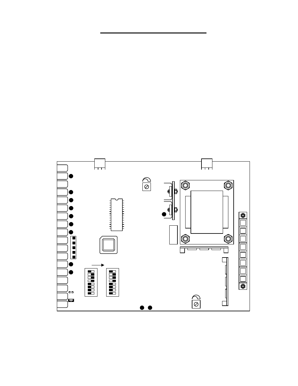
• Set the DIP-switches on the circuit board to the desired setting. See switch-setting charts in
section 3.2.
• Auto close timer (when turned on) can be set from 1 second (full counter clockwise) to
approximately 23 seconds (full clockwise).
• Dry contact relay (terminals 15-16) can be set for Normally Open (NO) or Normally Closed
(NC) operation by placing the relay shorting bar on the NO or NC pins respectively.
• Power LED indicates that low voltage power is applied to the circuit board. Input LEDs should
be OFF and will only illuminate when the input is activated. The pulse LEDs will blink as the
operator is running. They can be either ON or OFF when the operator is stopped.
1 2
3
4 5
6 7
8
ON
1 2
3
4 5
6 7
8
Timer
Reverse
Sensitivity
Power
Counter
LEDs
Relay Contact
Exit
Loop
Reverse
Loop
Figure 29
9100-065-D-5-07
Page
35