Controlled Products Systems Group 1601-080 User Manual
Page 31
1601-065-G-6-12
29
REVERSE
SENSITIVITY
TIME
DELAY
POWER
1
ON
2
3
4
5
6
7
8
1
ON
2
3
4
5
6
7
8
NC NO
UP
LOOP
DOWN
LOOP
1 2 3 4 5 6 7 8
9
10 11 12 13
14
1601
SW 1
SW 2
Com
N.O.
CLAS
S
CE
RT
IFIE
D
TO
CAN/C
SA
C22
.2
NO.
247
CONF
ORMS
TO
ANSI/UL-32
5
VEH
IC
ULA
R G
ATE
OP
ER
ATO
R
HP
533
82
MODE
L
SERIAL
VOL
TS
PHAS
E
AM
PS
60
Hz
MAX
GA
TE LOAD
Doo
rKin
g, In
c., In
gle
wo
od,
CA
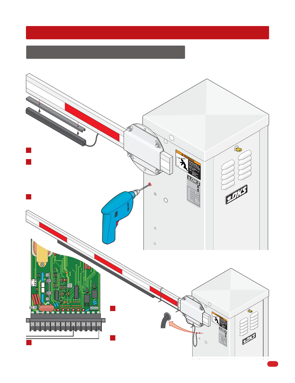
Mounting Channel
Reversing Edge
Turn operator power OFF.
Center and secure the 6-foot mounting
channel to the bottom of the barrier arm
using 3/4-inch wood screws (not supplied).
Slide the reversing edge into the mounting
channel.
Drill a 1/4-inch hole on the side of the
operator housing beneath the
operator arm shaft.
7.1 Contact Sensor (Reversing Edge)
SECTION 7 - OPTIONAL ACCESSORIES INSTALLATION
In addition to the electronic reversing device (ERD) an optional electric reversing edge (P/N 8080-016) may be installed offering
additional protection to the arm, operator and obstruction.
Connect wires to terminals 9 and
14 without interfering with any of
the operator’s moving parts.
CLA
SS
CE
RT
IFIE
D T
O
CA
N/C
SA
C2
2.2
NO
. 2
47
CO
NF
OR
MS
TO
AN
SI/
UL
-32
5
VEH
ICU
LA
R G
AT
E OP
ER
AT
OR
HP
533
82
MO
DE
L
SER
IAL
VO
LTS
PH
AS
E
AM
PS
60 H
z
MA
X GA
TE L
OA
D
Do
orK
ing
, In
c., I
ngle
wo
od,
CA
Wire Loop
Plastic
Grommet
Reversing Edge Assembly
Wire T
ie
Wire T
ies
1
2
3
4
5
6
Secure the wire to the arm and hub
using wire ties (not supplied). leave
a wire loop to allow the arm to
rotate freely.
Install a plastic grommet
(Not supplied) in the
hole to protect the wire
from chaffing on sharp
metal edges.