1 mounting hub, Arm direction and bracket hole positions, Vertical – Controlled Products Systems Group 1601-080 User Manual
Page 20
1601-065-G-6-12
18
CLA
SS
CER
TIFI
ED
TO
CA
N/C
SA C22.2 N
O. 247
CO
NFO
RMS TO
AN
SI/U
L-325
VE
HICU
LA
R G
AT
E O
PER
ATO
R
HP
53382
MO
DEL
SER
IAL
VO
LT
S
PH
ASE
AMPS 60
Hz
MAX G
ATE LO
AD
Door
Ki
ng,
Inc
., Ingl
ewoo
d, CA
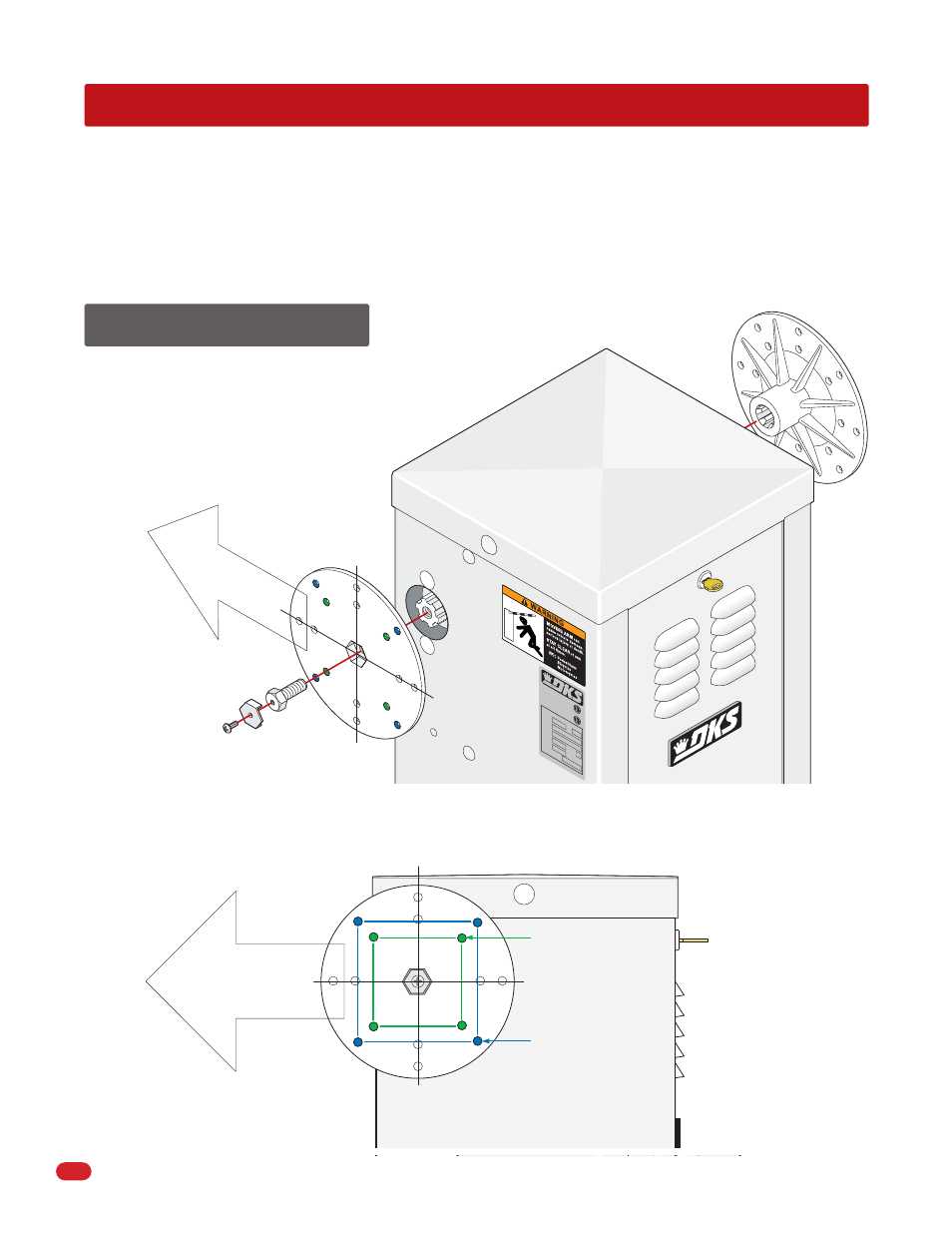
4.1 Mounting Hub
(
s
)
Hub
Second Hub
Locking
Plate
Bolt
Screw
Horizontal
Vertical
Mount hub(s) as shown with operator in the DOWN position.
A single hub should be mounted on the opposite side of
oncoming traffic.
Hub in the DOWN position.
Arm Direction
Wood bracket holes
(See next page).
Plastic/Aluminum
bracket holes
(See next page).
Horizontal
Arm Direction
V
ertical
Arm Direction and Bracket Hole Positions
SECTION 4 - ARM INSTALLATION
Arm installation varies depending on the operator model and individual installation requirements. All operators are equipped
with 2 hub connections on opposite sides of the operator.
The 1601 operates with a single 14 ft. arm (either straight or folding arm). The 1601 can not operate with the 20 ft. to 27 ft.
3-piece arm assemblies.
The 1602 operator is designed for the 3-piece 20 ft. to 27 ft. arm assemblies only.
Hub
Note: If your installation does NOT allow the
arm to mount in this direction, see Section
5.3, (page 24) to reverse factory setup.