Controlled Products Systems Group 106753 User Manual
Page 8
8
FAAC Model 770 24V Underground Swing Gate Operator
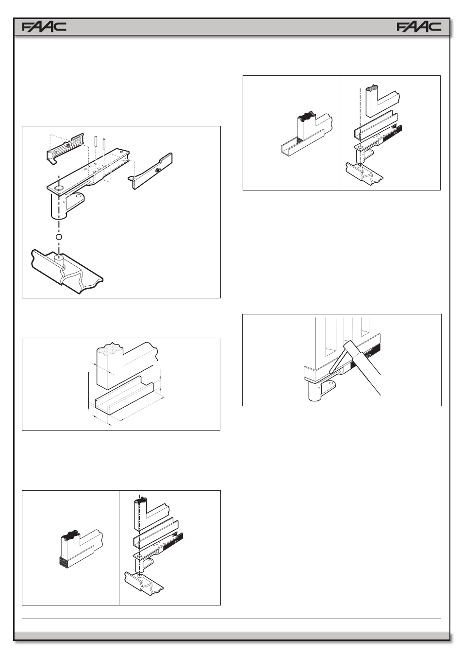
min ⅜
13
min 1½
C
C+1
Fig. 9
• Determine the correct location of the leaf on the “U” profile
with reference to the axis of rotation (Fig. 10a and 10b);
• Seal the “U” profile on the post side with a plate, as shown
in Figs. 10a and 10b.
Fig. 10a
Fig. 11
Fig. 10b
3.4
INSTALLING THE OPERATOR
1. Open the gate leaf.
2. Place the operator on the fastening screws on the foun-
dation box, and fix it by means of the supplied nuts and
washers (Fig. 13).
Note: the exact position of the operator is shown in Fig. 12. In
any case, the operator pinion must be on the opposite side of
leaves opening direction.
3. Manually close the leaf and fit the driving levers supplied,
as shown in Fig. 13.
Note: grease the operator pinion and the fixing pivots of the
two levers.
4. Install the second operator, if required, by repeating the
operations described above.
5. Install the electronic control unit. Refer to the relative
instructions.
6. Fasten the box cover by means of the supplied screws
(Fig. 14)
.
2. Prepare the guide bracket, as follows:
• Use a “U” profile with dimensions indicated in Fig. 9.
3. Carefully weld the guide bracket to the support bracket
(Fig. 11).
4. Fit the gate into the guide bracket and fix the top hinge in
place.
IMPORTANT: To ensure trouble-free operation, do NOT weld
the gate leaf to the guide bracket or to the support bracket.
5. Manually verify whether the gate opens and closes com-
pletely and smoothly, stopping at the mechanical travel
stops.
* Measurements
in Inches
3.3
SETTING UP THE GATE
Allow cement to set before starting this operation.
1. Assemble the release levers on the support bracket, and
fit the latter on the pivot in the foundation box, also inser-
ting the ball supplied (Fig. 8).
Note: grease both the pivot and the ball.
Fig. 8