Backup battery – Controlled Products Systems Group 106753 User Manual
Page 24
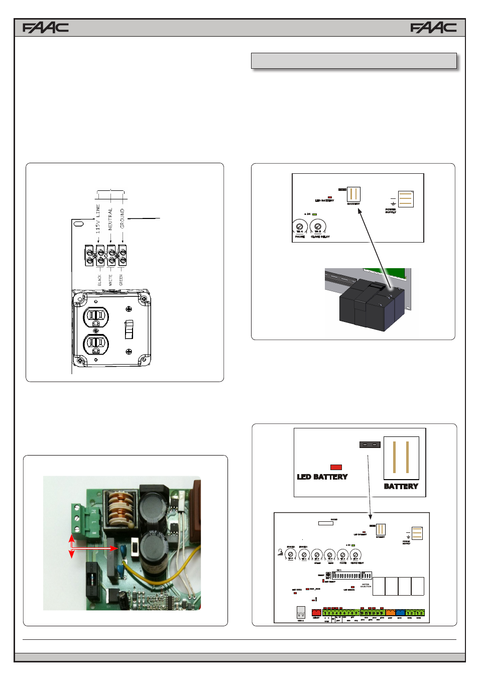
AC POWER CONNECTION
To connect AC power to the controller:
1. Turn the circuit breaker for the AC gate operator power OFF
before connecting the AC input wires.
2. Turn OFF the Power Switch located on the left side of enclo-
sure before connecting the AC input wires.
3. Connect the AC input wires to the AC terminal located on the
top left of the control box. See diagram below.
4. Batteries must be installed after the AC power is on. See
Battery Power Connection.
115V 60Hz 2.5A
The E024U board is powered by a high efficiency switching power
supply that takes 115V or 230V in input and provides 36VDC to
power the board. The power supply is preset for 115V at the fac-
tory, consult with FAAC Tecnical Support for 230V wiring options.
230V
115V
The E024U board allows the connection of a 24V backup bat-
tery to provide power to operate the gate during blackouts. For
more details about how the boards handles the loss of main
power and how to configure its behaviour please see par 4.3
and DS1 switch 7.
To connect the battery use the provided cable and plug it on the
BATTERY connector on the board. Plug the other end of the
cable to the batteries, red wire to +24 and black wire to GND.
SETTING
+
DL 1 DL 2 DL 3 DL 4 DL 5
J24
SETTING
+
DL 1 DL 2 DL 3 DL 4 DL 5
J24
SETTING
+
DL 1 DL 2 DL 3 DL 4 DL 5
J24
To disable the battery charger unplug jumper J24
J24 PRESENT = BATTERY CHARGING ACTIVE
J24 NOT PRESENT = BATTERY CHARGING NOT ACTIVE
9. BACKUP BATTERY
8.1 POWER SUPPLY
9.1 DISABLE THE BATTERY CHARGER
A14
E024U CONTROL BOARD