Sx dx, Installation steps – Controlled Products Systems Group 104572 User Manual
Page 8
8
FAAC Model 390 24V Articulated Arm Swing Gate Operator
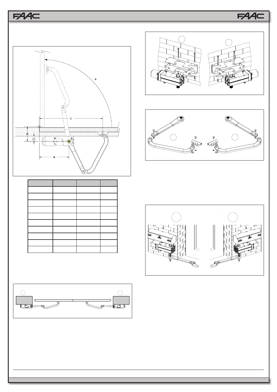
4.2.3. RECOMMENDED DIMENSIONS FOR OUTWARD
OPENING "overhead” swing mounting dimensions
A
B
C (max)
α
2⅜ - 4⅜
4⅜ - 5⅛
28¾
90°
4⅜ - 6¼
4⅜ - 5⅛
28¾
90°
6¼ - 8¼
4⅜ - 5⅛
28
90°
8¼ - 10¼
4⅜ - 5⅛
27½
90°
10¼ - 12¼
4⅜ - 5⅛
27⅛
90°
12¼ - 14⅛
4⅜ - 5⅛
26⅜
90°
2⅜ - 4⅜
7½ - 8¼
23½
120°
4⅜ - 6¼
9 - 9⅞
22
120°
6¼ - 8¼
11⅜ - 12¼
19
120°
8¼ - 10¼
12¼ - 13
17¼
120°
SX
DX
SX
DX
Fig. 8
Fig. 9
Fig. 10
Establish the installation position of the operator by consulting
Figs. 4-6.
4.3.
INSTALLATION STEPS
The operator 390, base-plate and articulated arm are designed
either for right-hand or left-hand (Fig. 7) installation.
• Secure the base-plate to the pilaster, using Ø10 screws
and suitable expansion plugs (Fig. 8), and ensure that it is
perfectly horizontal.
• Fit the gearmotor unit on the base-plate and secure it with
the two screws, nuts and flexible washers (Fig.8).
•
The transmission shaft must always face downward.
•
Assemble the articulated arm and front coupling as
shown in Fig. 9.
•
Fit the straight lever of the articulated arm on the gear-
motor shaft and tighten it with the supplied screw and
washer (Fig. 10).
•
Release the operator (See Chapter 5)
DX
SX
SX
DX
Fig. 7
Fig. 6a
• Measurements in Inches
•
Establish the securing position of the front coupling on the
leaf, observing dimension “C” defined previously (Section
4.2). Check that arm and coupling are perfectly horizontal.
•
The coupling may be welded directly onto the leaf (Fig. 11)
or screwed by using the threaded inserts (Fig. 12).
•
In both cases, temporarily remove the coupling from the
arm in order to secure it.
•
Fit the cover on the operator (Fig. 10).
•
Re-lock the operator (See Chapter 5)
•
Make the electrical connections of the selected electronic
appliance, observing the annexed instructions.