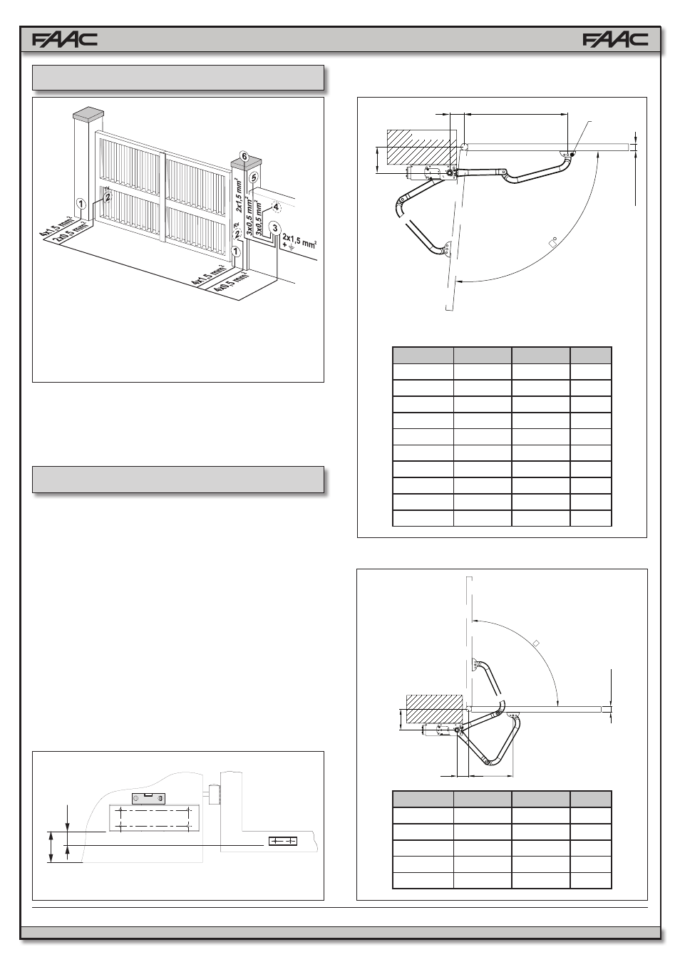
Electrical layout 4. installation, Preliminary checks, Installation dimensions – Controlled Products Systems Group 104572 User Manual
Page 7
7
FAAC Model 390 24V Articulated Arm Swing Gate Operator
C
B
A
°
1½ / 2
⅜
1½
7⅞
A
B
C
1½ / 2⅜
X
Fig. 3
Fig. 6
Fig. 4
Fig. 5
4.1.
PRELIMINARY CHECKS
To ensure safety and an efficient automation, make sure
the following requirements are met:
• The gate structure must be suitable for automation. In
particular, make sure it is sufficiently sturdy and rigid,
and that its dimensions are in line with those indicated
in the technical specifications.
• Make sure that the leaves move properly and uniformly,
without any irregular friction during their entire travel.
• Check if hinges are in good condition.
• Make sure the travel limit mechanical stops are pres-
ent.
• We advise you to carry out any metalwork jobs before
installing the automation.
4.2.
INSTALLATION DIMENSIONS
1)
Operators Model 390
2) Photocells
3)
Electronic Equipment
4)
Key-Operated Push-Button
5)
Radio Receiver
6)
Warning Light
1. To lay electrical cables, use adequate rigid and/or
flexible tubes.
2. Always separate low voltage accessories from those
operating at 115V~. To avoid any interference, always
use separate sheaths.
• Measurements in Inches
• Measurements in Inches
Notes:
As for 120° openings, the curved arm must be fixed to
the hole marked with the letter X
3. ELECTRICAL LAYOUT
4. INSTALLATION
4.2.1. RECOMMENDED DIMENSIONS FOR INWARD
OPENING
4.2.2. RECOMMENDED DIMENSIONS FOR OUTWARD
OPENING
A
B
C (max)
α
2⅜ - 4⅜
4⅜ - 5⅛
28¾
90°
4⅜ - 6¼
4⅜ - 5⅛
28¾
90°
6¼ - 8¼
4⅜ - 5⅛
28
90°
8¼ - 10¼
4⅜ - 5⅛
27½
90°
10¼ - 12¼
4⅜ - 5⅛
27⅛
90°
12¼ - 14⅛
4⅜ - 5⅛
26⅜
90°
2⅜ - 4⅜
7½ - 8¼
25½
120°
4⅜ - 6¼
9 - 9⅞
23⅝
120°
6¼ - 8¼
11⅜ - 12¼
21¼
120°
8¼ - 10¼
12¼ - 13
20
120°
A
B
C (max)
α
2⅜ - 4⅜
4⅜ - 5⅛
17
90°
4⅜ - 6¼
4⅜ - 5⅛
15
90°
6¼ - 8¼
4⅜ - 5⅛
13
90°
8¼ - 10¼
4⅜ - 5⅛
11
90°
10¼ - 12¼
4⅜ - 5⅛
9½
90°
• Measurements in Inches
Operators Cable Size
AWG 14 (max 30’)
AWG 12 (max 50’)
AWG 10 (max 100’)