Mount the photoelectric sensors, Entrapment protection wiring options, Entrapment protection – Controlled Products Systems Group CDO MD L/H Hoist 1/2hp 115v User Manual
Page 18: Primary installation: cps-u photoelectric sensors
18
^^^^
XA
N
T
ANT
D14
COM
INTRLK
STOP
LED
OPEN
CLOSE
TTC
LEARN
1
LMEP1
LMEP2
23
4
5
6
7
ST
OP
CLOSE
OPEN
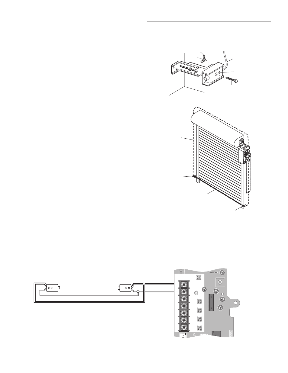
PRIMARY INSTALLATION: CPS-U PHOTOELECTRIC SENSORS
(White)
(White/Black)
NOTE: When installing model CPS-UN4, connect the brown wire to
terminal 1 and the blue wire to terminal 2.
ENTRAPMENT PROTECTION WIRING OPTIONS
ENTRAPMENT PROTECTION
MOUNT THE PHOTOELECTRIC SENSORS
Center each sensor in the bracket with the lenses pointing
toward each other across the door.
Attach the sensors to the brackets with the provided
hardware. Finger tighten the receiving sensor wing nut.
Securely tighten the sending sensor wing nut.
Run the wires from both sensors to the operator. Use
insulated staples to secure wire to the wall and ceiling.
Connect the sensor wires to the operator.
1
2
3
4
Wire
Indicator Light
“C” Wrap
Wing Nut
1/4"-20x1-1/2" Hex Bolt
Sensor
Photoelectric Sensor
6" (15 cm) max. above floor
Invisible Light Beam Protection Area
Bell Wire
Secure wire with
insulated staples
Connect wire
to Operator
Photoelectric Sensor
6" (15 cm) max. above floor