Controlled Products Systems Group SK-1323-SDQ User Manual
Page 4
ENFORCER Outdoor Stand-Alone Keypads
4
SECO-LARM U.S.A., Inc.
Important Notes
IF USING THE KEYPAD WITH A MECHANICALLY OPERATED DOOR OR
GATE, MOUNT THE KEYPAD AT LEAST 5’ (15m) FROM THE DOOR OR
GATE TO PREVENT USERS FROM BEING CRUSHED OR PINNED.
FAILURE TO DO SO MAY RESULT IN SERIOUS INJURY OR DEATH.
!
!
1. Always disconnect power before servicing the keypad.
2. The keypad must be properly grounded. Use a minimum 22AWG wire connected to the Uninsulated
Chassis Ground wire. Failure to do so may damage the keypad.
3. All wiring and programming should be done by a professional installer to reduce the risk of
improper installation.
4. Basic keypad functions are located on page 16 of this manual. Be sure to store this manual in a safe
place for future reference.
5. If using VAC, use the Green Common Ground wire for all sensor input.
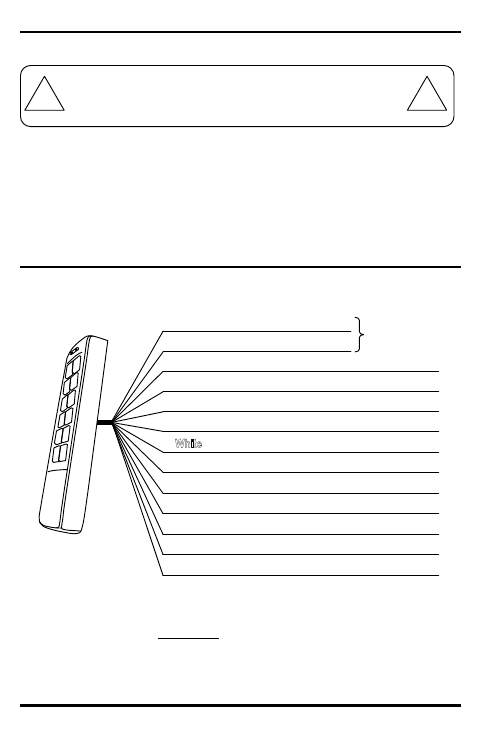
Wiring Diagram
*Chassis Ground: Connect a continuous wire from the Uninsulated Chassis Ground wire to a grounding
point to avoid damage from static discharge. A good grounding point could include a grounded metal
conduit, a cold water pipe, or a grounding rod. Use 18AWG wire for earth ground for best results. Wire
used must be at least 22AWG.
SK-2323 series shown. Wiring is the same for both series.
Black
Red
Brown
Orange
Yellow
Green
Pink
Aqua
Ground (-)
Power (+)
Door Sensing Input (N.C.)
Egress Input #1 (N.O.) Triggers Output #1
Egress Input #2 (N.O.) Triggers Output #2
Common Ground (-)
Output #1 (N.O.)
Blue
Purple
Gray
Output #1 (COM)
Output #1 (N.C.)
Output #2 (N.O.)
Output #2 (COM)
Output #2 (N.C.)
12~24 VAC/VDC
Uninsulated Chassis Ground*