6 detail wiring, Page 14 – Controlled Products Systems Group 1520-080 User Manual
Page 14
Page 14
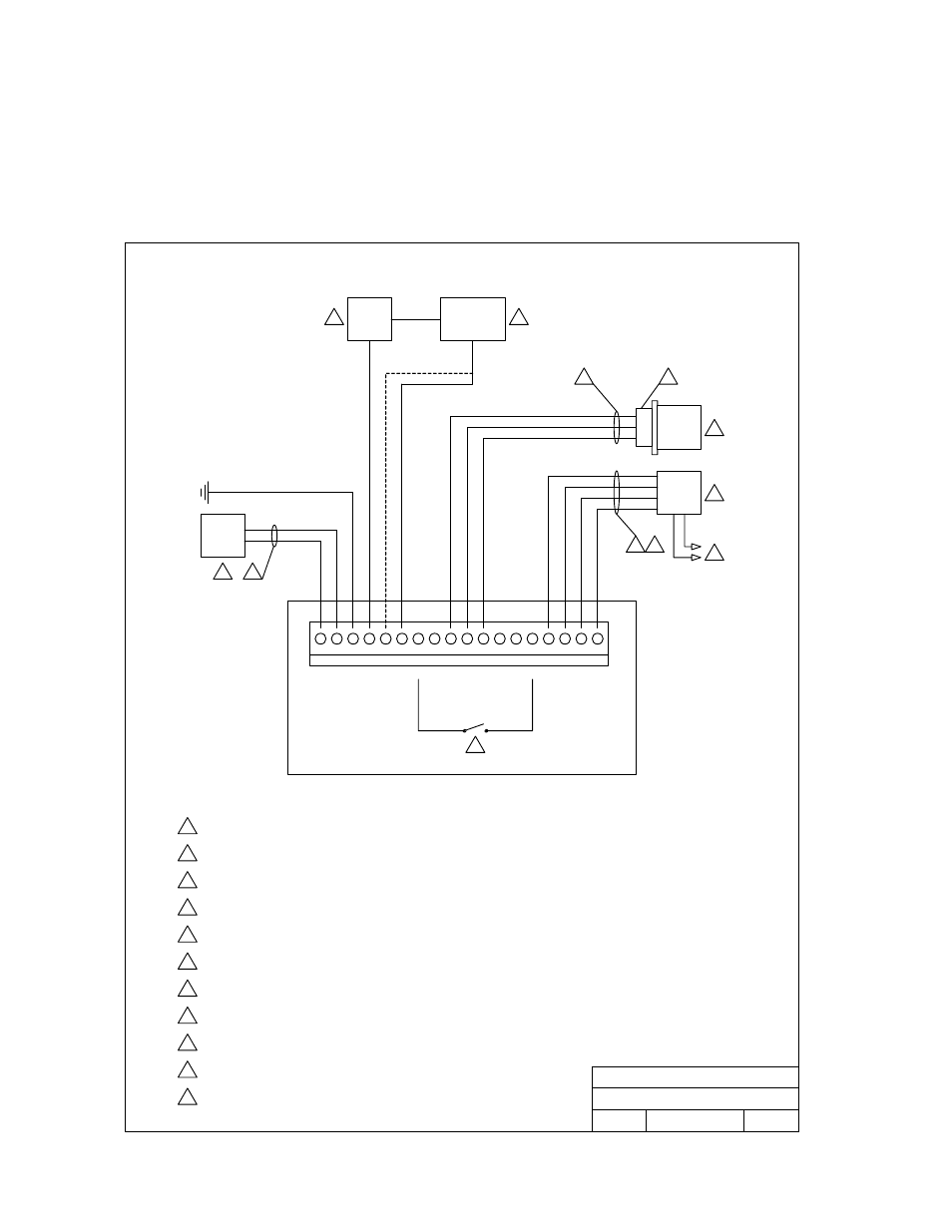
1.6 Detail
Wiring
DOORKING, INC., INGLEWOOD, CA 90301
Title:
Date:
Rev.
Dwg. No.
1
2
3
4
5
6
7
8
9 10 11 12 13 14 15 16 17 18
PWR
INPUT
LOCK
PWR
STRIKE/
MAG LOCK
CARD
RDR
PRNTR
GR
N
WH
T
BL
K
RE
D
GR
N
WH
T
BL
K
1
5
3
4
6
8
9
10
7
11
6
DOORKING
1520-010
Belden 9418 or Equivalent. 500 Ft. max.
16 Volt, 20 VA UL Listed Transformer.
12-24 VDC may also be used to power the 1520.
Power for door strikes or magnetic locks is not provided by the
system. It must be provided by an external power supply.
4
5
6
7
1
2
3
8
2
Wire size determines maximum wire run distance. See chart on previous page.
Electric Strikes are wired to Normally Open (N.O.) contacts;
magnetic locks are wired to the Normally Closed (N.C.) contacts.
A switch closure across terminals 7 and 14 will activate the relay
for its programmed strike time. Connect postal switch here.
If reader is lighted, use Belden 9931 (6-conductor). 500 Ft. max.
Power for lights must be provided from a separate
source. Do not connect to terminals 1 and 2.
9
Card reader is built into and pre-wired on the 1520-080. Wiring is shown
for the 1520-081 controller.
10
11
Optional Serial Printer - P/N 1508-067.
DB-25 Adapter - P/N 1587-010.
1
2
3
Detail Wiring
Model 1520 Card Reader / Controller
5/02
M1520-065-1
A
Model 1520 Card Reader / Controller
Detail Wiring