2 1520-080 card reader installation – Controlled Products Systems Group 1520-080 User Manual
Page 10
Page 10
1.2
1520-080 Card Reader Installation
Do not mount the card reader to a moving gate, or immediately next to a gate panel or pedestrian
gate. Continuous vibration from slamming gates and vibration can cause damage to the system over
time.
WARNING! If the card reader is used to activate a vehicular gate operator, it
must be mounted a minimum of 10 feet away from the gate and gate operator,
or in such a way that the user cannot come into contact with the gate or gate
operator while using the device.
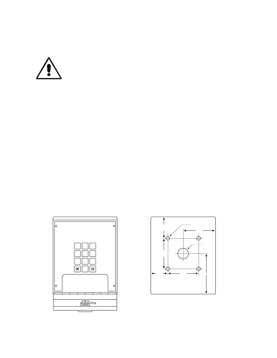
1.
Open the faceplate of the card reader with the keys provide so that the programming
keypad is exposed.
2.
Remove four (4) 6-32 x ¼ screws from the corners of the keypad mounting plate.
Save these screws as they will be used to re-install the mounting plate.
3.
Carefully remove the keypad and circuit board assembly.
4.
Carefully pull up on the terminal connector to disengage the proximity reader head
from the circuit board. Set the circuit board aside.
5.
Mount the back box. Connect conduits and route wiring into the box at this time. Be
sure to clean out the back box of any debris that can cause a short.
6.
Install the memory chip (see Section 1.4). Be sure that power is OFF!
7.
Make necessary wire connections at this time (see Section 2).
8.
Re-install the terminal connector onto the circuit board by carefully pushing it down
onto the connector.
9. The
default
MASTER CODE is 9999. If the master code is to be changed, refer to
Section 3.1 to reprogram the master code prior to re-installing the keypad mounting
plate. The memory chip must be installed and the system powered to change the
master code.
10.
Re-install the keypad mounting plate using the four (4) 6-32 x ¼ screws removed in
step 2.
5
8
0
2
1
4
7
9
6
3
2 1/
2
2 1/2
1 7/
8
1 3/8
2 5/8
3
5/16 DIA
7/8 DIA
Back View