Figure 7 - unit address programming example – CTI Products TIB TSAM Interface User Manual
Page 19
TIB Hardware Reference
Comparator Wiring Lists
CTI Products, Inc.
68-10911-100
14
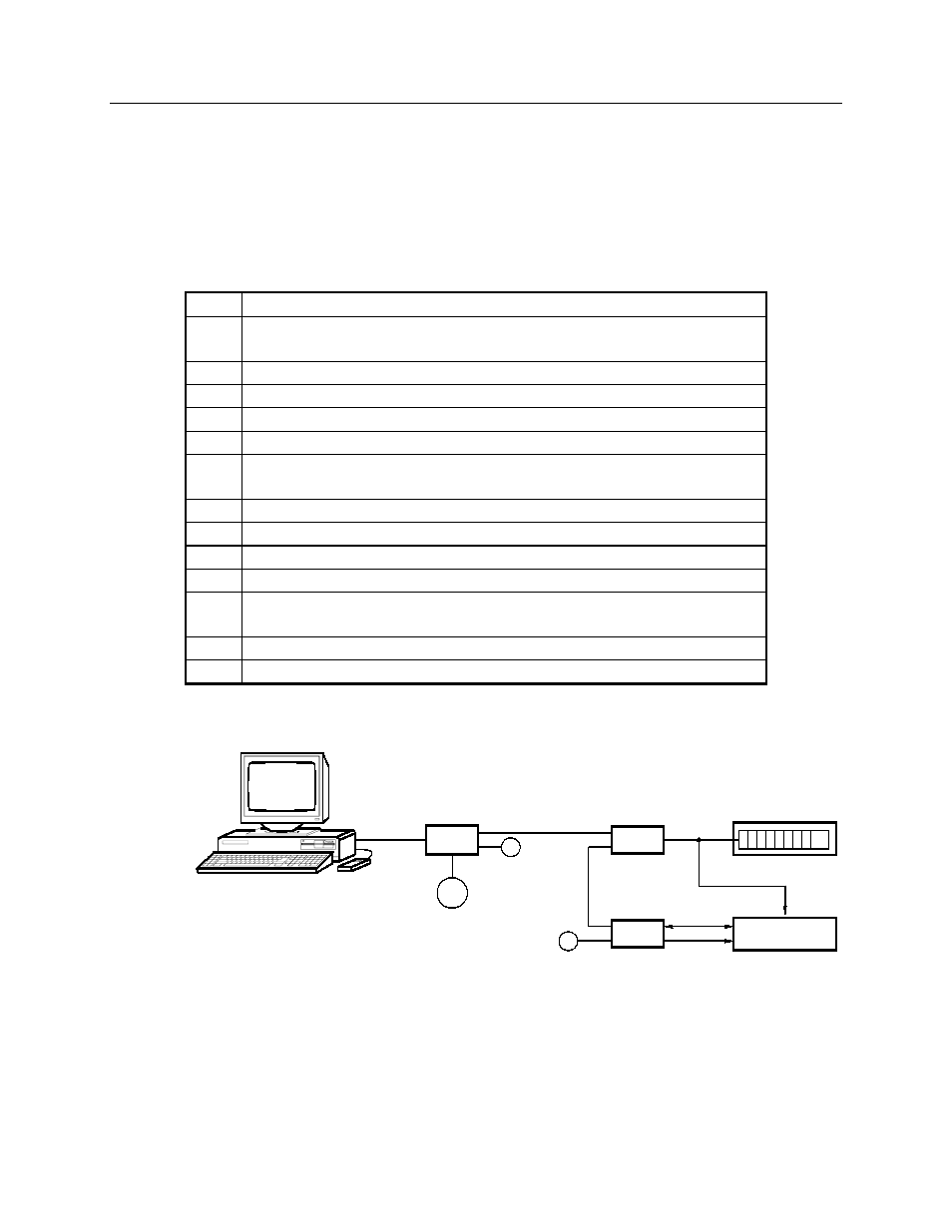
For example, Figure 7 shows a system with a single TIB and CIB. The following
steps show how the system might be setup, using the following address
assignments:
• CIB address is Group 00, Module 0
• TIB address is Group 01, Module 0
• HIB address is Group 80, Module 0 (this is set using the MCNCFG
program running on the Local PC)
Step
Action
1
Connect the module’s NETWORK IN and OUT ports as shown in
the diagram.
2
Power on the modules.
3
On the CIB, set the Group switch to 00 and the Module switch to 0.
4
Reset the CIB.
5
On the TIB, place OPTION switch 4 in the UP position.
6
On the TIB, set the Group switch to 00 and the Module switch to 0.
This is the address of the CIB it will work with.
7
On the TIB, set the transmitter bank selector switches to bank 0.
7
Press the RESET button on the TIB.
8
The TIB’s ERR LED will turn on and remain on.
9
On the TIB, place OPTION switch 4 in the DOWN position.
10
On the TIB, set the Group switch to 01 and the Module switch to 0.
This is the TIB’s own address.
11
Press the RESET button on the TIB.
12
The ERR LED will turn on momentarily and then turn off.
COM 2
COM 1
CA-80119-100
CIB
1
COMPARATOR
HIB
P/S
OUT
IN
T
IN
OUT
IN
OUT
T
TSAM
TIB
VOTE LINES
FORCE SELECT
TX SELECT
LOCAL PC
Figure 7 - Unit Address Programming Example