Table 21 - sub-category selection, Table 22 - custom text for sub-category system – CTI Products IOB I/O Interface User Manual
Page 32
IOB Hardware Reference
System Examples
CTI Products, Inc.
68-11168-105
27
Since there are two sub-categories defined in this system, we need to reserve one
of the I/O bits for the sub-category selector. Figure 9 shows that I/O bit 4 (FAIL)
is reserved for the sub-category selector. Because I/O bit 4 is reserved, we cannot
use any IOB I/O pins that correspond to I/O bit 4 (see Table 16) as general
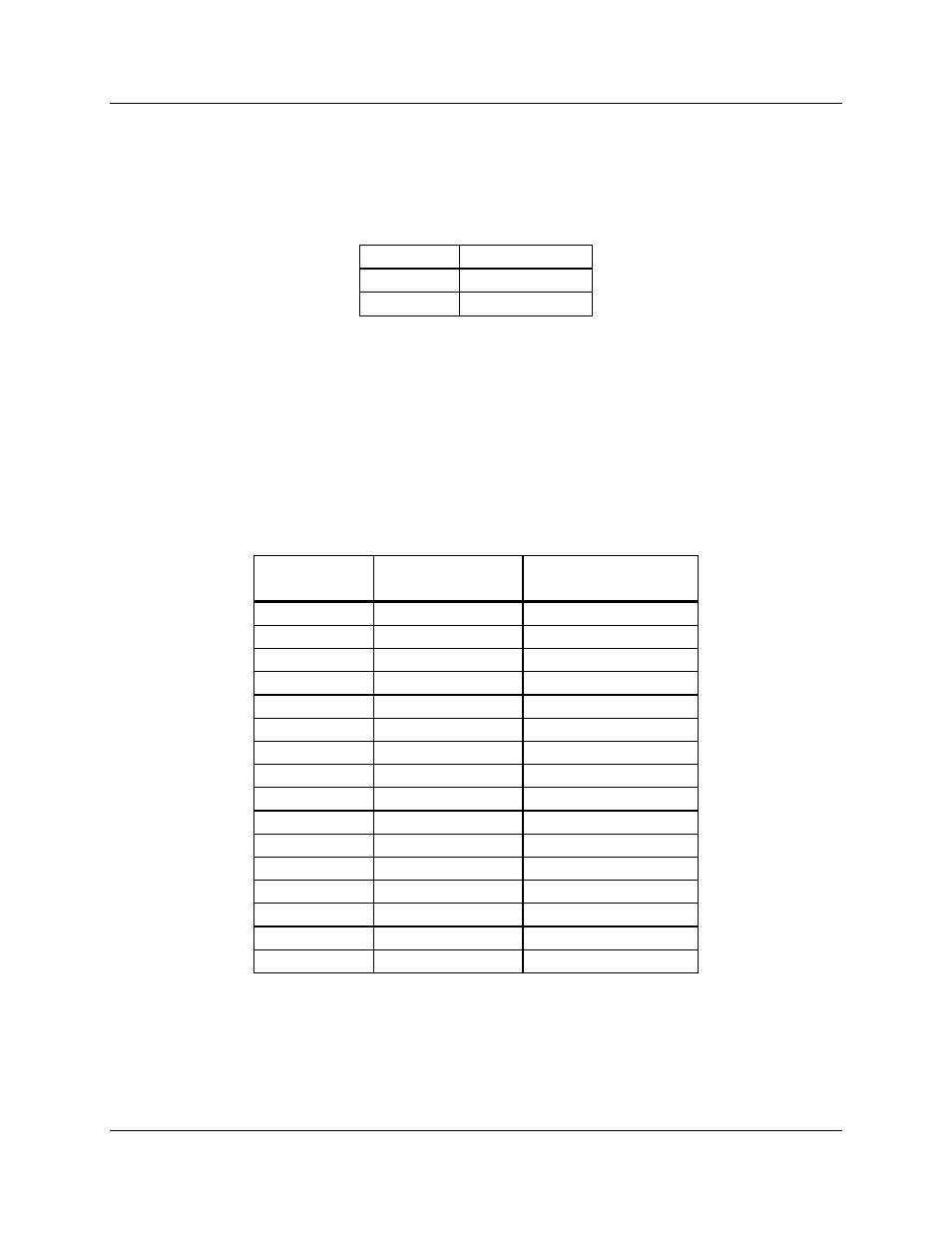
purpose I/O pins. Table 21 shows how the sub-category selector bit operates.
I/O Bit 4
Sub-category
0
Alarm
1
Control
Table 21 - Sub-category Selection
When I/O bit 4 is inactive (the input is floating), the Alarm sub-category text is
selected and when it is active (the input is tied to ground), the Control sub-
category is selected.
Using the I/O group definitions shown in Figure 9, we can create a custom text
table for all possible input value field combinations. Table 22 shows the custom
text messages and the corresponding input value fields.
Input Value
Field
Active I/O Bit
Combinations
Custom
Text
00
-
01
1
Alarm
04
2
Active
05
2 + 1
Act/Alrm
10
3
Fail
11
3 + 1
Fail
14
3 + 2
Fail
15
3 + 2 + 1
Fail
40
4
41
4 + 1
On
44
4 + 2
Off
45
4 + 2 + 1
Error
50
4 + 3
Full
51
4 + 3 + 1
Full/On
54
4 + 3 + 2
Full/Off
55
4 + 3 + 2 + 1
Error
Table 22 - Custom Text for Sub-category System
From this table we can now create our custom status text category in the
MCNRCD.CFG file. Refer to the appendix in the Monitoring and Control
Network Remote Comparator Display Software Manual (reference 2) titled
Changing Status Message Text for details about the format of the MCNRCD.CFG
file.