Table 20 - 1 of 4 select example custom text – CTI Products IOB I/O Interface User Manual
Page 29
IOB Hardware Reference
System Examples
CTI Products, Inc.
68-11168-105
24
CA-80276-100
CIRCUIT
USER APPLICATION
IOB
CIRCUIT
1
2
3
4
I/O BIT
I/O GROUP
(INPUT)
(OUTPUT)
1-4
TX SELECT
PTT
NO CONNECT
NO CONNECT
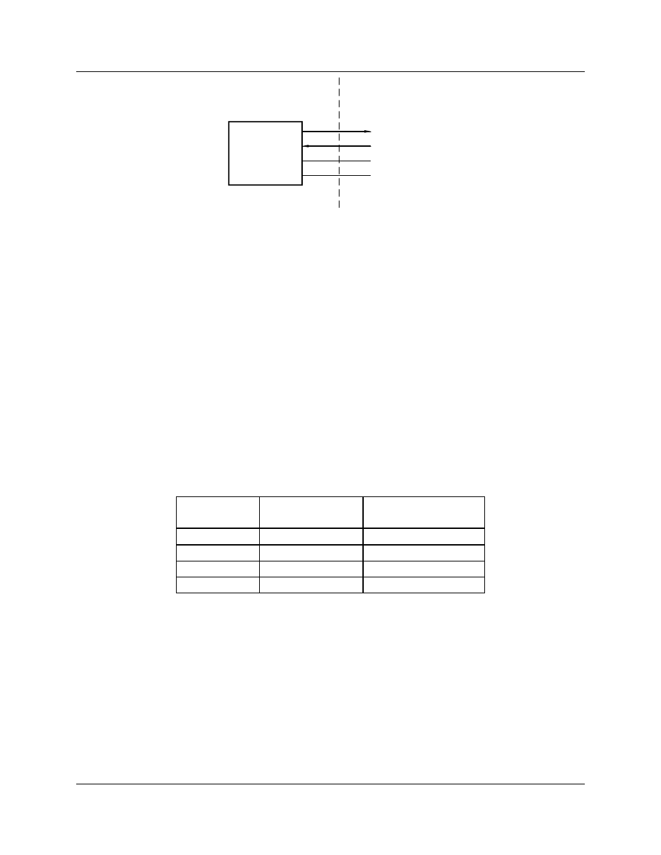
Figure 7 - 1 of 4 Select I/O Bit Configuration (Tx Select and PTT)
From the figure, you can see that relay control lines are connected to the Select 1A
through D outputs of the IOB. These outputs correspond to I/O bit 1 of I/O
groups 1 through 4 . The PTT inputs are connected to four input lines of the IOB,
which correspond to I/O group bits 2 (RECEIVE) and 4 (FAIL) of I/O groups 5
through 8.
Before editing the MCNRCD.CFG file, we need to define our custom text
messages. Let’s define the status messages for the active Select output line to be
the text Active and the status messages for the active input lines to be Tx. Now
we can create a custom text table for all possible input value field combinations.
Table 20 shows the custom text messages and the corresponding input value
fields.
Input Value
Field
Active I/O Bit
Combinations
Custom
Text
00
-
01
1
Active
04
2
Tx
05
1 + 2
Act/Tx
Table 20 - 1 of 4 Select Example Custom Text
From this table we can now create our custom status text category in the
MCNRCD.CFG file. Refer to the appendix in the Monitoring and Control
Network Remote Comparator Display Software Manual (reference 2) titled
Changing Status Message Text for details about the format of the MCNRCD.CFG
file.