Mode 1 - general purpose i/o - 16 outputs, Mode 2 - two sets of 1 of 4 select output, Table 5 - 1 of 4 select operation – CTI Products IOB I/O Interface User Manual
Page 13: Table 6 - inverted select a operation
IOB Hardware Reference
Theory of Operation
CTI Products, Inc.
68-11168-105
8
3.2
Mode 1 - General Purpose I/O - 16 Outputs
In general purpose I/O mode, the IOB module provides 16 input/output lines and
16 input only lines. Table 16 shows the pinout for this mode as well as the I/O
group and I/O bit number associated with each connector pin.
3.3
Mode 2 - Two Sets of 1 of 4 Select Output
In this mode, the IOB provides two sets of 1 of 4 Select output lines and 24 input
only lines. Table 16 shows the pinout for this mode as well as the I/O group and
I/O bit number associated with each connector pin.
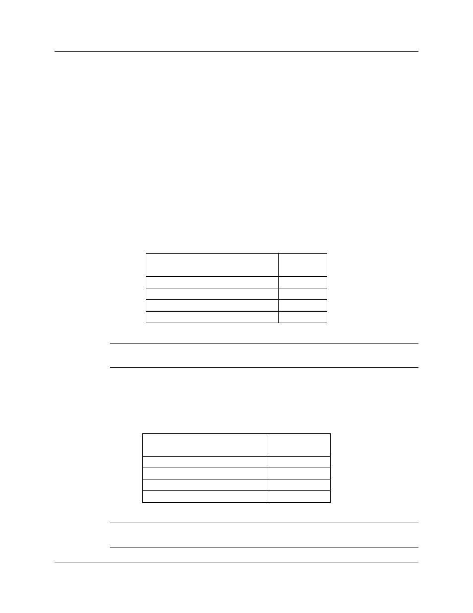
Table 5 shows how the 1 of 4 Select outputs operate, allowing only one active
output in each set of 4 Select lines (A, B, C and D). Remember, the outputs are
active low so the output pin for the selected output is low and the output pins of
the other select outputs are high.
Select 1 or Select 2
A B C D
selected
output
1 0 0 0
Select A
0 1 0 0
Select B
0 0 1 0
Select C
0 0 0 1
Select D
Table 5 - 1 of 4 Select Operation
Note: In this table, any output shown as a 0 is a high output and any output shown
as a 1 is low output.
The IOB has the option to invert the Select A output so that the Select A output
pin is active high and the Select B, C and D output pins are active low. This
operation is shown in Table 6. The Select A invert option is selected with
OPTION switch position 3 (see section 4).
Select 1 or Select 2
A B C D
selected
output
0 0 0 0
Select A
1 1 0 0
Select B
1 0 1 0
Select C
1 0 0 1
Select D
Table 6 - Inverted Select A Operation
Note: In this table, any output shown as a 0 is a high output and any output
shown as a 1 is low output.