Connectors, Figure 4 - network in/out ports, Table 15 - network connector pinout – CTI Products IOB I/O Interface User Manual
Page 22
IOB Hardware Reference
Connectors
CTI Products, Inc.
68-11168-105
17
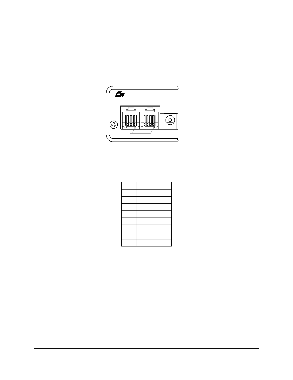
5. Connectors
The NETWORK IN/OUT ports on the front of the IOB are used to connect the
IOB with other MCN modules. These ports carry both the network data signals as
well as DC power for power distribution with other modules. . Table 15 gives the
pinout for these connectors. Figure 4 shows the location of pin 1 for each port.
CA-80068-100
DC IN
IN
OUT
NETWORK
PRODUCTS, INC.
PIN 1
Figure 4 - Network IN/OUT Ports
Pin
Function
1
DATA +
2
DATA -
3
+ POWER
4
No Connect
5
No Connect
6
- POWER
7
- POWER
8
+ POWER
Table 15 - Network Connector Pinout
The DC IN port provides the primary power connection to the module. Power is
distributed through the NETWORK OUT connector to provide power to the
NETWORK IN connector of the MCN unit it is connected to. Each power
supply can power up to four units total. See the Monitoring and Control Network
System Manual (reference 1) for complete details of connections to the network
and DC IN connectors.
Connector J1 provides the discrete I/O points. The pin definitions for this
connector change, depending upon which operating mode the IOB module is set
for. Table 16 gives the pin numbers and their definitions for each mode. The
column labeled I/O bit includes, in parenthesis, the MCNRCD name associated
with the bit number. Table 17 gives this same information, but the order of the
IOB pin numbers matching a punch block pinout. See the appendix titled