CNB INS1000 User Manual
Page 8
XNET Network Video Server User’s Guide
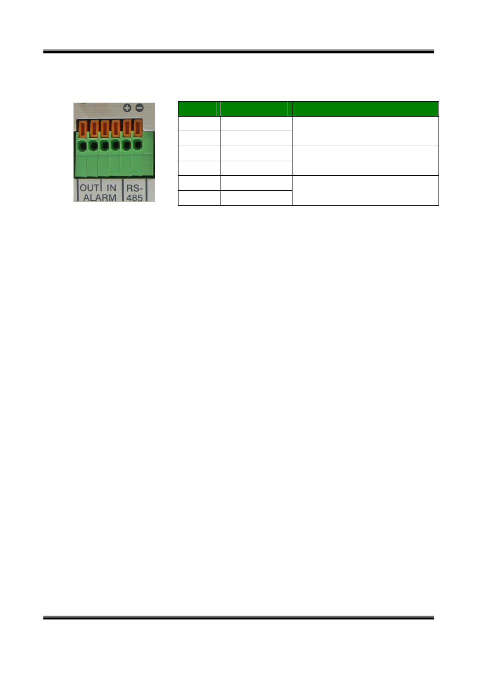
y RS-485 and ALARM IN/OUT : Used for connecting P/T device, sensor, and alarm devices
to XNET. Pin assignments are as follows
Pin
Description
Misc.
1 Alarm
Out
2 Alarm
Out
Relay output : closed circuit in
alarm to indicate alarm status.
3
Alarm In (+)
4
Alarm In (-)
NC/NO selectable in admin mode.
5 RS485
+
6 RS485
+
1 6
RS-485 : Used for connecting Pan/Tilt and Zoom devices having RS-485
interface standard.
Alarm In : Connect external alarm sensors such as the infrared sensors, heat
sensor, magnetic sensors, etc. NC/NO selectable in the admin page.
Alarm Out : It is used for connecting external alarm generators such as sirens,
flashing light, etc. When activated, relay output configures a closed circuit.
Please refer to Section 6.1 for more detailed description on the Alarm In/Out
connections.
y Reset :
Factory Default Switch
There is a switch provided for returning the network camera to factory default state. Press
the switch about 3 seconds through a tiny hole at the left of the 100BaseT connector using
tools with sharp tip for a few seconds while power is applied.
8 of 44