See section “6.1. alarm-in and alarm-out – CNB IG1810PF User Manual
Page 8
XNET Network Box Camera User’s Guide
y 1
aseT
: 100Mbps Ethernet connector (RJ-45) with proprietary PoE.
00B
S-2
- Status LED: Green color indicates that the camera is in normal operation mode, while red
color indicates that the camera is in abnormal condition.
When connecting a power source to the XNET, the status LED will be lit red for a
second and then it will change to green.
- Link LED: Continuous yellow light means that network cable is plugged in. It will flicker
when there is traffic.
y R
32C & Video-out: 3 Pins from the bottom of the connector are assigned for RS-
232
port, while the remaining 2 pins are used for checking composite video output from the
camera. Please note that the bottom most pin is numbered as 1.
Pin
Description
Misc.
1
TxD of RS-232C
2
RxD of RS-232C
3
Ground of RS-232C
For debugging & factory
use only.
4
Video out from the camera
For use in installation.
5
Ground for Video out.
For use in installation
5
1
y 1
C:
Power input of XNET/XNET-Wireless.
Do not apply power through this power input when power is applied through LAN cable using
proprietary PoE.
2VD
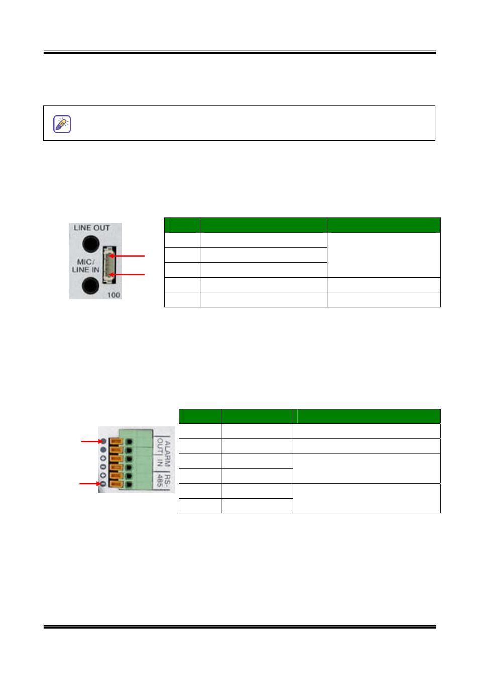
y RS-485 and ALARM IN/OUT: Used for connecting P/T device, sensor, and alarm devices to
XNET/XNET-Wireless. Pin assignments are as follows
Pin
Description
Misc.
1 RS-485
(-)
2 RS-485
(+)
3
Alarm In (-)
4
Alarm In (+)
NC/NO selectable in admin mode.
5 Alarm
Out
6 Alarm
Out
See section “6.1. ALARM-IN
and ALARM-OUT”
6
1
- RS-485
:
Used for connecting Pan/Tilt and Zoom devices having RS-485 interface standard.
- Alarm In:
Connect external alarm sensors such as the
infrared sensors, heat sensor,
magnetic sensors, etc. NC/NO selectable in the admin page.
-
Alarm Out:
It is used for connecting external alarm generators such as sirens, flashing light,
etc. When activated, relay output configures a closed circuit.
Please refer to Section 6.1 for more detailed description on the Alarm In/Out connections.
8 of 47