Clock Audio MR 88 User Manual
Page 3
Page 3
INTRODUCTION
The purpose of this manual is to assist programmers in successfully writing
code to control the MR88 automatic mixer. This manual describes the RS232
interface to the MR88 automatic mixer.
When more than one MR88 is linked via the Link In/Out connectors, the
RS232 control will extend through the link. Any MR88 in the chain can be
used as the RS232 input. The MR88’s are automatically addressed from 1 to
n. The first MR88 in the chain is Mixer 1
RS232 Physical Parameters
The MR88 is controlled via RS232: 38400 baud, no parity, 8 data bits 1 stop
bits.
The physical connection is to the DB9 way connector on the MR88 rear
panel.
Pin 2
Rx data to PC.
Pin 3
Tx data from PC.
Pin 5
Ground.
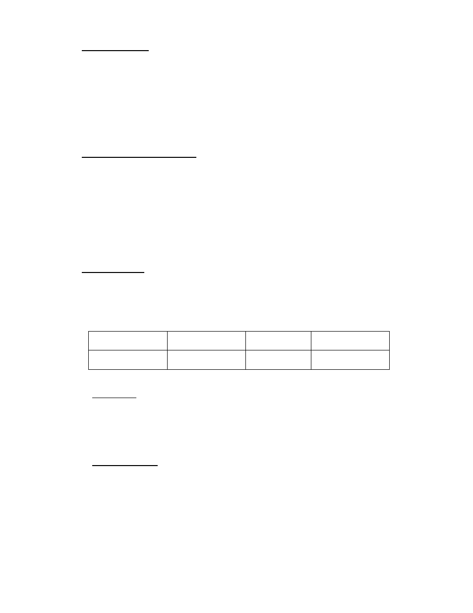
RS232 Packets
All RS232 packets, whether they are transmitted to, or received from the
MR88 mixer, use the same packet format. All values are in bytes using
unique headers and footers with byte stuffing. In this manual, a byte is
represented by a hexadecimal number in the form 0xNN.
Packet Header
Data
Checksum
Packet Footer
1 byte ( 0x7E )
N bytes
1 byte
1 byte ( 0x7D )
Checksum
The one-byte checksum is calculated as the 1’s complement of the sum of
the data bytes, modulo 256 before byte stuffing. Therefore the sum of all the
data bytes including the checksum will be 0xFF. If the data or checksum
contains any reserved bytes they are replaced with a 2 byte sequence.
Reserved Bytes
0x7D becomes 0x7F 0xFD
0x7E becomes 0x7F 0xFE
0x7F becomes 0x7F 0xFF