ADTRAN DDS-DP User Manual
Page 7
7
61433105L2-5D
Section 61433105L2, Issue 4
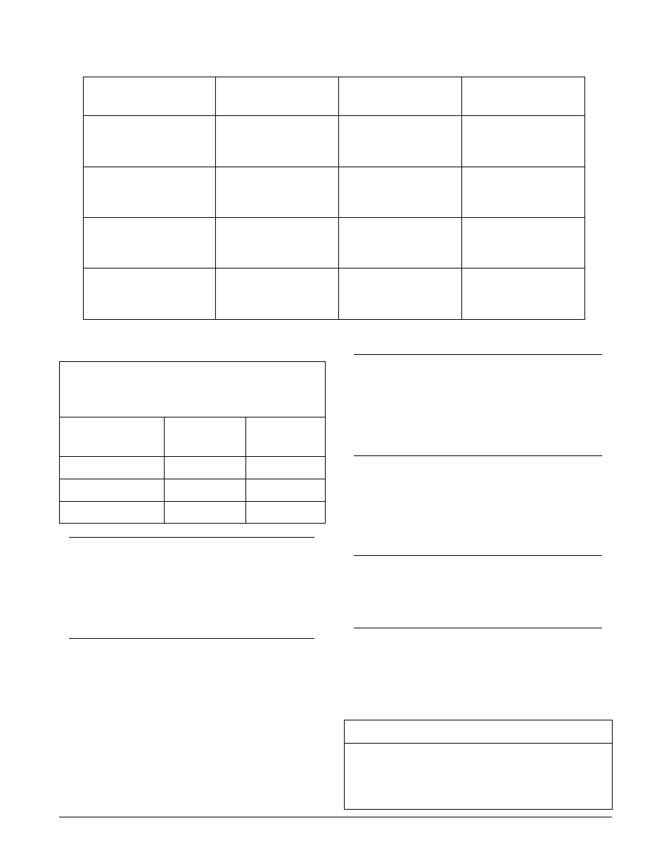
Table 6. Series 5 Total Reach DDS Insertion
Loss Measurements
S
D
D
l
a
n
o
i
t
i
d
a
r
t
r
o
f
z
H
k
8
2
o
t
d
e
r
a
p
m
o
c
z
H
k
3
.
3
1
e
c
i
v
r
e
s
S
D
D
e
n
i
L
n
o
i
t
a
r
u
g
i
f
n
o
C
n
o
i
t
a
r
u
g
i
f
n
o
C
n
o
i
t
a
r
u
g
i
f
n
o
C
n
o
i
t
a
r
u
g
i
f
n
o
C
n
o
i
t
a
r
u
g
i
f
n
o
C
z
H
k
3
.
3
1
@
z
H
k
8
2
@
G
W
A
6
2
t
f
k
7
2
B
d
2
1
.
0
5
B
d
5
3
.
5
6
G
W
A
4
2
t
f
k
5
2
.
6
3
B
d
0
0
.
0
5
B
d
0
5
.
2
6
G
W
A
2
2
t
f
k
0
5
B
d
4
2
.
0
5
B
d
3
3
.
9
5
Table 5. Cable Type and Temperature Loss Data @ 13.3 kHz
E
L
B
A
C
C
I
T
S
A
L
P
t
f
k
/
S
S
O
L
B
d
E
L
B
A
C
R
E
P
A
P
t
f
k
/
S
S
O
L
B
d
)
F
0
(
C
I
P
e
g
u
a
G
9
1
)
F
0
7
(
C
I
P
e
g
u
a
G
9
1
)
F
0
2
1
(
C
I
P
e
g
u
a
G
9
1
2
0
3
5
.
0
3
8
0
6
.
0
0
1
6
6
.
0
)
F
0
(
P
L
U
P
e
g
u
a
G
9
1
)
F
0
7
(
P
L
U
P
e
g
u
a
G
9
1
)
F
0
2
1
(
P
L
U
P
e
g
u
a
G
9
1
6
1
6
5
.
0
5
1
4
6
.
0
5
5
9
6
.
0
)
F
0
(
C
I
P
e
g
u
a
G
2
2
)
F
0
7
(
C
I
P
e
g
u
a
G
2
2
)
F
0
2
1
(
C
I
P
e
g
u
a
G
2
2
2
1
9
.
0
8
5
2
0
.
1
5
1
0
1
.
1
)
F
0
(
P
L
U
P
e
g
u
a
G
2
2
)
F
0
7
(
P
L
U
P
e
g
u
a
G
2
2
)
F
0
2
1
(
P
L
U
P
e
g
u
a
G
2
2
4
5
4
9
.
0
6
0
6
0
.
1
0
7
3
1
.
1
)
F
0
(
C
I
P
e
g
u
a
G
4
2
)
F
0
7
(
C
I
P
e
g
u
a
G
4
2
)
F
0
2
1
(
C
I
P
e
g
u
a
G
4
2
1
7
5
2
.
1
2
8
9
3
.
1
7
1
9
4
.
1
)
F
0
(
P
L
U
P
e
g
u
a
G
4
2
)
F
0
7
(
P
L
U
P
e
g
u
a
G
4
2
)
F
0
2
1
(
P
L
U
P
e
g
u
a
G
4
2
0
0
9
2
.
1
4
2
3
4
.
1
8
6
2
5
.
1
)
F
0
(
C
I
P
e
g
u
a
G
6
2
)
F
0
7
(
C
I
P
e
g
u
a
G
6
2
)
F
0
2
1
(
C
I
P
e
g
u
a
G
6
2
1
5
7
6
.
1
9
6
4
8
.
1
8
0
6
9
.
1
)
F
0
(
P
L
U
P
e
g
u
a
G
6
2
)
F
0
7
(
P
L
U
P
e
g
u
a
G
6
2
)
F
0
2
1
(
P
L
U
P
e
g
u
a
G
6
2
3
2
8
6
.
1
8
6
5
8
.
1
8
1
7
9
.
1
NOTE
Measure noise with 50 kbit weighting
characteristic approximating a filter with a
passband of 40 Hz to 30 kHz. Background
noise level or impulse noise level is referenced
from 56/64 kbps data rate in TR62310.
6. MAINTENANCE
The Total Reach DDS-DP does not require routine
maintenance for normal operation.
Compliance Requirements
CAUTION
This product for installation in a restricted
access location in a Type B or E enclosure
only.
Max input current @ max load = 165 mA @ -48 Vdc.
Max output current @ max load = 41 mA @
-140 Vdc.
NOTE
The 50 dB AML limit includes 6 dB of signal
margin to account for potential near-end
cross talk (NEXT) from other digital services
that may be provisioned in the same binder
group.
•
Loop length should not exceed 50 kft.
•
Bridged tap length should not exceed 12 kft.
•
Background noise level should not exceed
34 dBrn.
•
Impulse noise should not exceed
-40 dBm, (+50 dBrn).
Table 7. Compliance Codes
Code
Input
Output
PC
F
C
TC
–
X
IC
A
–