2 electronic boards connectors, 3 main board connections, Installation 3.7.2 electronic boards connectors – Hach-Lange ORBISPHERE 410 User Manual User Manual
Page 31
29
Installation
3.7.2 Electronic boards connectors
Connectors P8 on the main board, and connectors J7 and J8 on the measurement board are
made of two parts. Push down carefully the black levers on either side of the connector and pull
it out securely. Perform all connections with these connectors unplugged. Once finished, attach
the connectors to the boards by pushing them firmly in place (levers up).
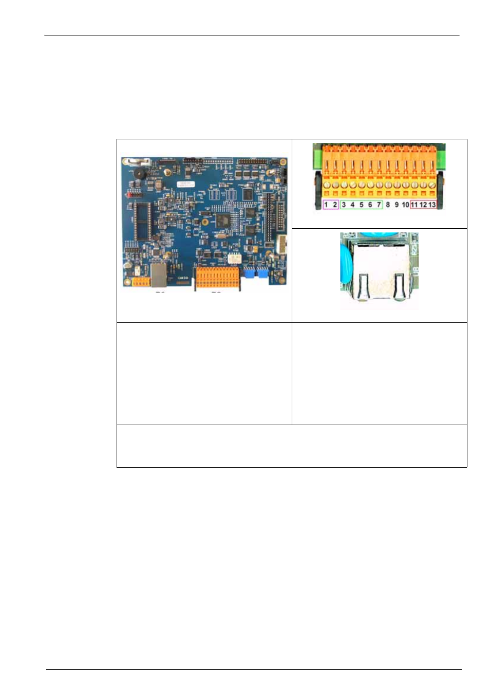
3.7.3 Main board connections
Figure 11 Main board
Figure 12 Connector P8
Figure 13 Connector P3
Connector P8:
1.
RS-485 (signal A)
2.
RS-485 (signal B)
3.
PROFIBUS-DP (GND)
4.
PROFIBUS-DP (+ 5 V)
5.
PROFIBUS-DP (signal -)
6.
PROFIBUS-DP (signal +)
7.
PROFIBUS-DP (signal RTS)
8.
Not used
9.
Not used
10.
Not used
11.
System alarm relay (N.O.)
12.
System alarm relay (N:C.)
13.
System alarm relay (Common)
Connector P3
Ethernet RJ 45. Connect the instrument to the local network by passing an ethernet cable
through the ethernet cable gland (location illustrated in
for the wall mount
and
for the panel mount). Connect to the P3 connector illustrated above.