External communications connection, Input/output connections, Sample tubes installation – Hach-Lange POLYMETRON 9240 Basic User Manual User Manual
Page 8: Input/output connections
4. Unscrew the cable gland nut, pass the power cable through it, and then up through the cable
gland and into the transmitter (No. 2). Screw back the cable gland nut to secure the power cable.
5. Open the transmitter front door by unscrewing the four holding screws.
6. Swing open the door (it is hinged to the left) to reveal the inside of the transmitter.
7. Remove the metallic shielding plate (No. 1) protecting access to the main board.
8. Remove the power supply connector (No. 3) and note where the earth, neutral and live (E, N, L)
must be connected.
9. Connect the power supply cables to the connector.
10. Put the connector back in place (No. 4).
11. Replace the metallic shielding plate, ensuring it is in front of the power cable just installed.
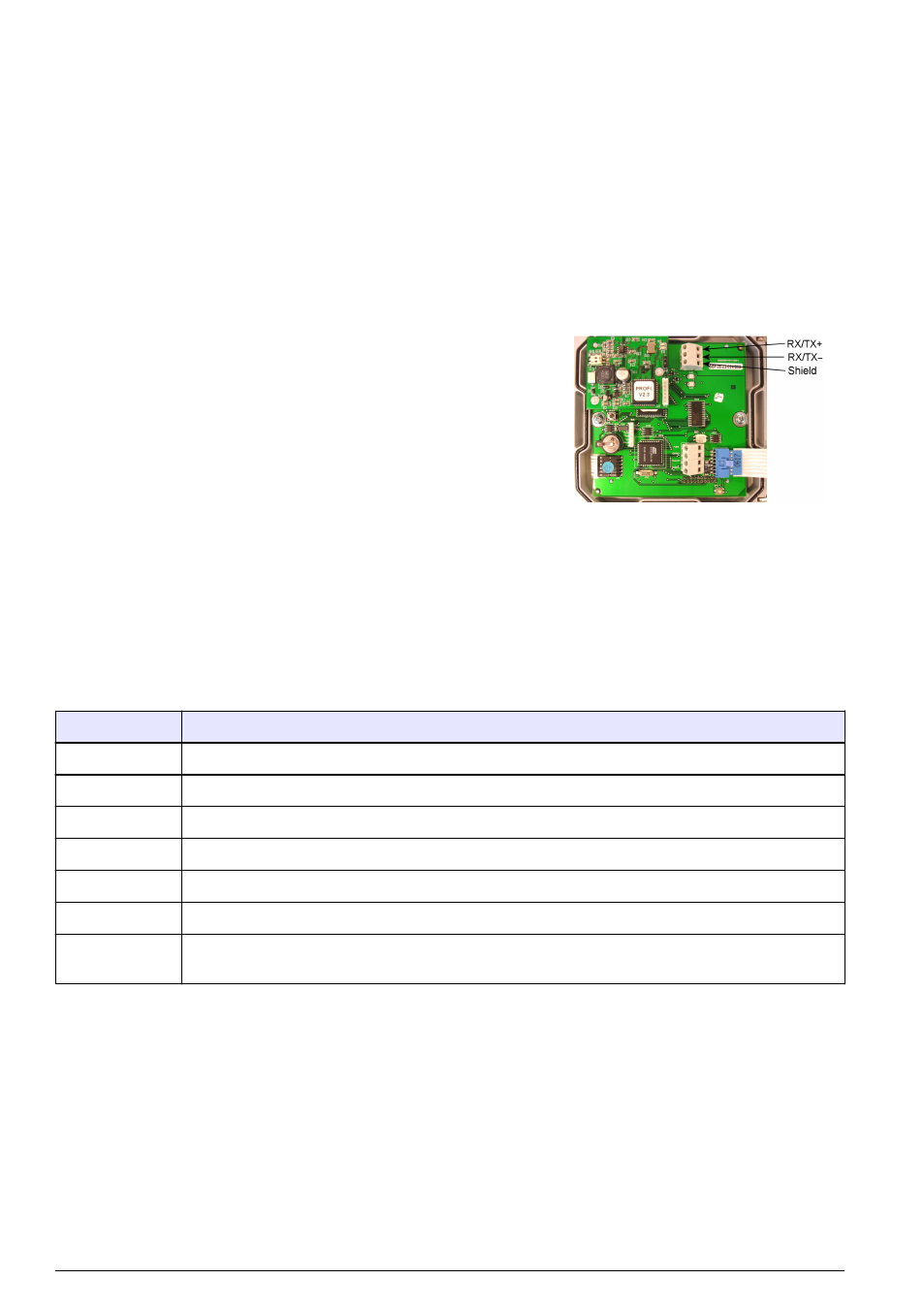
External communications connection
1. Run the communications cable through an external cable gland on
the bottom of the cabinet, and into the analyzer.
2. Pass it through the cable gland located right and farthest from you
on the base of the transmitter, so it appears inside the transmitter
through the left front cable gland.
3. Connect the communication cable as indicated. Connection is the
same on the CPU board for both the JBUS/ MODBUS and
PROFIBUS options.
4. Close the transmitter door and secure in place with the 4 screws.
5. Put the local controller box back in its normal position and secure in
place with the 2 holding screws.
Input/Output connections
Before using any of the cable glands, perforate first with a screwdriver. To ensure a good seal, the
external diameter of the cables should be between 5 and 7 mm. The nomenclature given in the
connections column of the following table refers to the same nomenclature that is printed on the I/O
board against each available connection.
Connections
Function
Re1 to Re6
on page 16 for more information on the relays
Re7
Warning alarm
Re8
System alarm
In2
For remote calibration
In4 to In7
By-pass channel measurement (channel 4 - 1 respectively)
Iout0
Used for the current measurement signals
Iout1 to Iout7
Can be freely linked to different parameters like measurement, temperature - refer to the
section entitled
on page 17 for details
On completion, close the local controller box (No. 11 in
on page 6) and secure in place with
the 6 screws.
Sample tubes installation
Connecting the sample
Use new tubes for connections during installation
• Exterior Ø: 6 mm exactly (or ¼'')
• Material: polyethylene or PTFE or FEP
• Flow rate: 6 to 9 L/hour
8 English