Fig. 12, Cleaning the throttle screw – Cashco 9540L P/P User Manual
Page 9
IOM-9540L
9
3.
If adjustments are made with the positioner
mounted on the control valve, the feedback lever
(13) on the main shaft (17) of the positioner must
be loosened. (See Section III:8-9).
a.
Set the changeover plate (15) to “N”.
b.
Turn the throttling screw (42) CW to its stops
(maximum GAIN).
c.
Unhook the range spring (41) from the flapper
lever (38).
d.
Check that the flappers (52) are aligned con-
centrically with the nozzles (51). If necessary
loosen the AMPLIFIER mounting screws on
the rear of the positioner and align the ampli-
fier (53) sub-assembly accordingly.
e.
Press the flapper lever (38) several times
alternately to the left and right, so that the ball-
and-socket mounted flappers (52) are aligned
parallel to the nozzles (51).
f.
Press the flapper lever (38) to the left. Set the
clearance between the right-hand nozzle (51)
and the right-hand flapper (52) to 0.6 mm
(0.024 in.) with the aid of feeler gauge by
turning the hexagonal adjuster (56) with a 6
mm wrench. Then secure the nut against
further turning using sealing paint.
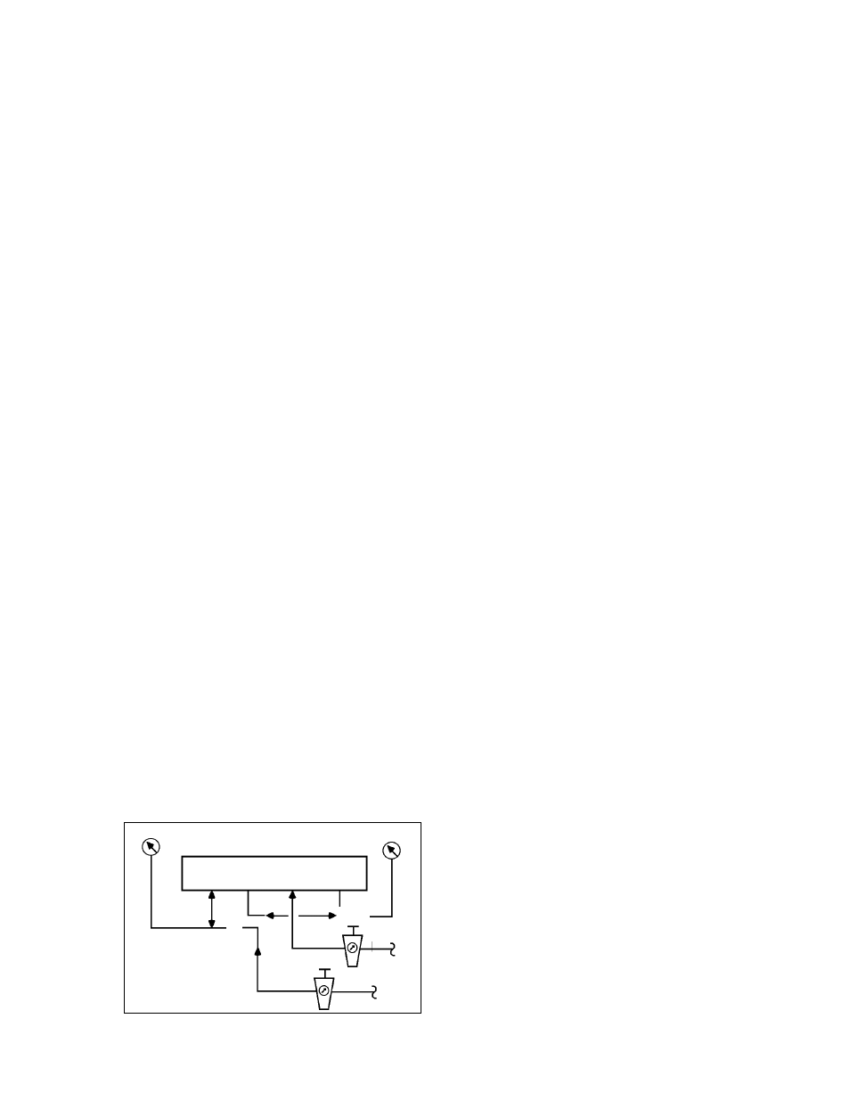
g.
Connect the positioner as shown in the test
circuit in Figure 12. Provide an “IAS” of 60
psig.
h.
Press the flapper lever (38) to the left. If the
output does not rise to the level of the supply
air pressure, either leaks are present of the
flapper (52) is not correctly aligned (repeat
e.).
I.
Hook the range spring (41) onto the flapper
lever (38), and provide a 9 psig input “SIG” to
port “Input (3-15) W” using a manual loader.
4.
The following procedure must be observed in
order to achieve a no-feedback adjustment of the
zero and stroke settings:
a.
Press the stroke factor lever (19) against the
travel stop pin (20).
b.
Set the stroke factor thumbscrew (40) to a
high stroke factor (approx. 5/64” before the
upper stop).
c.
Turn the zero thumbscrew (39) until the out-
put pressure is 9 psig and make a note of this
value.
d.
Set the stroke factor thumbscrew (40) to a low
stroke factor (approx. 5/64 before the lower
stop). The output pressure may not vary by
more than
±
0.003 psig as compared with the
setting described in c. above.
e.
In case of excessive deviations the travel stop
pin (20) should be adjusted. Whenever the
travel stop pin (20) is adjusted, the settings
described in b. -to- d. should be repeated until
the deviation is less than
±
0.003 psig.
f.
Seal the travel stop pin (20) with sealing paint.
5.
For mounting see Section III.
6.
Return the changeover plate (15) to its original
position if it was “U”. Re-tighten the feedback (13)
lever onto the main shaft (17) of the positioner
(See Section III.B.8 & 9.).
B. Cleaning The Throttle Screw: (See Figure 10)
1.
Unscrew CCW the limiting screw (43). If you can’t
pull it out by hand, unscrew CCW the throttle
screw (42) and remove both by hand.
2.
Pull the throttle screw (42) out of the limiting screw
(43).
3.
Place the throttle screw (42) in a solvent (e.g.
benzene) and blow through it carefully. It is best to
clean in an ultrasonic solvent bath.
4.
Turn the throttle screw (42) in again as far as it
goes CW.
5.
Turn the limiting screw (43) in as far as it goes CW;
then back it out CCW about half a revolution.
6.
Secure the limiting screw (43) with sealing paint.
Figure 12
Test Gauge
Test Gauge
MANUAL
LOADER/
AIRSET
IAS
IAS
SIG
3-15 psig
See Table 2
for pressure
required
Input
W
Output
1
Supply Air
Output
2
LOAD