Replacing the amplifier, Fig. 13, Trouble shooting guide – Cashco 9540L P/P User Manual
Page 10
IOM-9540L
10
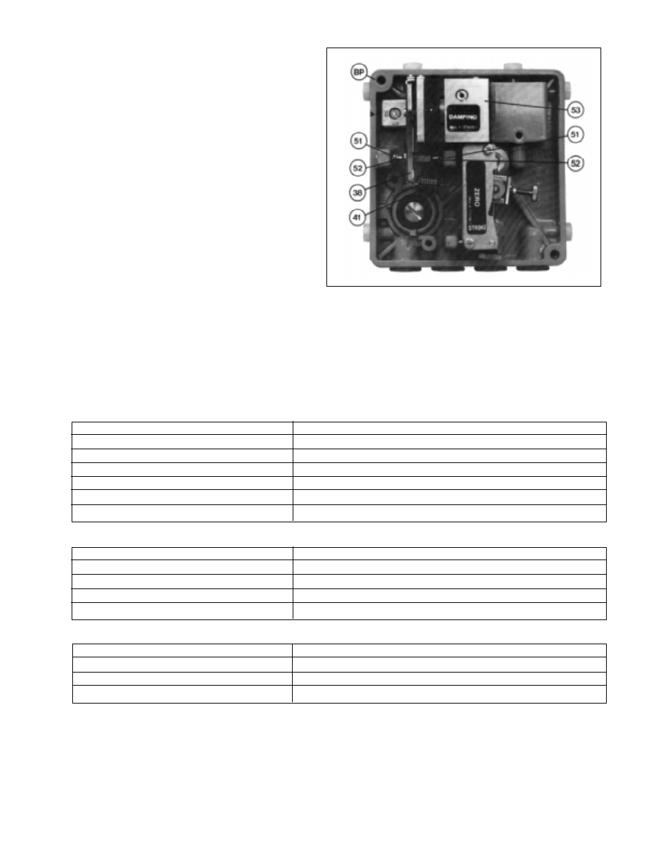
C. Replacing The Amplifier: (See Figure 13)
1.
Unhook the range spring (41) from the flapper
lever (38). (See Figure 11.)
2.
Unscrew and remove the amplifier (53) sub-
assembly; the two amplifier mounting screws are
accessible from the rear of the positioner.
3.
Install a new amplifier (53). Do not forget the
O-rings between the amplifier and the baseplate
(BP) (air baffle). Before tightening, carefully align
the mounting screws, position the amplifier (53) in
such a way that the flappers (52) are concentri-
cally aligned with the nozzles (51).
4.
Hook the range spring (41) onto the flapper lever
(38).
5.
Perform a maintenance basic adjustment and
recalibrate per Sections IV, V and VI.
VII.
TROUBLE SHOOTING GUIDE
1.
Actuator does not respond to applied input signal.
Possible Causes
Remedies
A. Amplifier defective
A1. Replace amplifier (See VI.C.).
B. Pneumatic connections reversed
B1. Check connections.
C. Feedback lever not tightened
C1. Screw feedback lever tight (See III.B.9.).
D. Stroke factor lever is loose on the shaft
D1. Tight shaft.
E. Positioner mounted on the wrong side
E1. Check mounting side in accordance with table in Section III.
F. Changeover plate in the wrong orientation
F1. Check setting accordance with table in Section III.
2.
Output pressure does not reach its maximum.
Possible Causes
Remedies
A. Amplifier throttle dirty
A1. Remove and clean throttle (See VI.B.).
B. Supply air too low
B1. Check supply air pressure.
C. Flappers not parallel with nozzles
C1. Align flappers (See VI.A.d.-f.).
D. Supply air filter dirty
D1. Replace filter.
3.
Actuator moves to end position.
Possible Causes
Remedies
A. Positioner mounted on wrong side
A1. Check mounting side in accordance with table in Section III.
B. Feedback lever not tightened
B1. Tighten feedback lever.
C. Stroke factor lever loose on shaft
C1. Tighten shaft (See Section III.B.).
Figure 13
SECTION VII