Basic adjustments/settings, Manual bypass setting, Fig. 7 – Cashco 9540L P/P User Manual
Page 5: Required tools, Tbl. 2
IOM-9540L
5
the connection port of the actuator casing.
NOTE-
Thread Sealants: If TFE tape is used, make sure
that small pieces of tape will not be “pinched off”
and enter the pneumatic internals. (Liquid thread
sealants are not recommended.)
11. Place temporary fittings and tubing so that the
positioner is able to be supplied with a 20-35 psig
air supply to the “SUPPLY AIR” port of the adapter
block (AB). Supply pressure depends upon actua-
tor bench range; see Table 2. Using a manual
loader, connect a 3-15 psig air source to the
“INPUT (3-15 psig) W” port of the adapter block
(AB).
12. Stroke the valve thru its full travel by varying the
input signal “SIG” span of 3-15 psig. Observe the
feedback linkage to assure that the linkage does
not bind and does experience overtravel. At a 9
psig signal input, the feedback lever should be
approximately horizontal.
IMPORTANT NOTE: If the feedback lever (13) is
turned forcibly against the travel stop pin (20), the
stroke factor lever (19) will be released from rigid
connection (unscrews) to the positioner main shaft
(17). If this occurs, the feedback lever (13) must
be loosened, the main shaft (17) must be retight-
ened to the stroke factor lever (19) by holding the
stroke factor lever (19) firmly against the travel
stop pin (20), while turning the main shaft (17) CW
(viewed from shaft end) using a screwdriver on the
main shaft’s (17) end. Steps 8 thru 11 must be
repeated.
13. Leave temporary air sources as installed for final
calibration, Section V, but turn off the air supply so
that no pressures are induced to the internals.
IV. BASIC ADJUSTMENTS/SETTINGS
A. Required Tools:
The following tools are required for the basic
adjustment:
1.
Screwdriver
2.
Open-end wrench - 6 mm
3.
Feeler gauge 0.6 mm (.024 in)
4.
(2) test gauges - 30 psig (for 20 psig max
bench range); (1) test gauge - 30 psig and
(1) test gauge - 60 psig (for 30 psig max bench
range)
5.
Manual loader/airset
6.
Open-end wrench - 10 mm
7.
Needle-nose pliers; small
8.
#5 Allen wrench (5 mm) (provided)
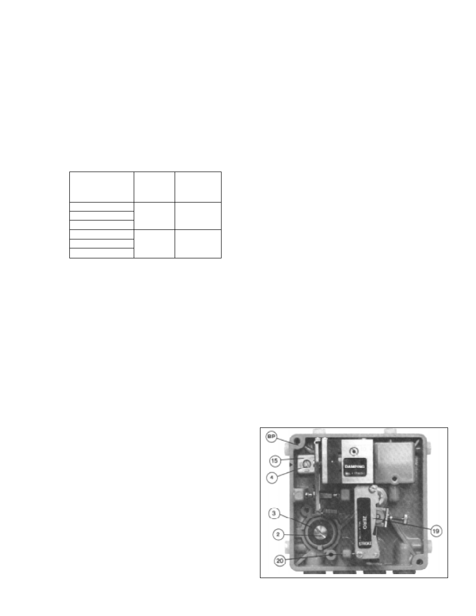
B. Manual Bypass Setting: (See Figure 7)
1.
There are two positions for the pneumatic
bypass switch (3) to be in:
“EIN”-Positioner is active (ON); this is the
factor set position.
“AUS” - Positioner is inactive (OFF), and the
input “SIG" is passed directly to the actuator,
bypassing the positioner internals.
2.
“EIN” or “AUS” are labels cast into the baseplate
(BP). To bypass, loosen the bypass screw (2)CCW
to release the bypass switch (3) rotor; two full
revolutions of the bypass screw (20) will be re-
quired. Rotate the bypass switch (3) CW 90
°
to
move to bypass (AUS); rotate CCW to activate the
positioner (EIN). The bypass switch (3) has a rib
on its outer edge that indicates the position of the
bypass switch (3). When adjustments are com-
pleted, retighten bypass screw (2). DO NOT
LEAVE AT AN INTERMEDIATE POSITION;
PLACE AT “EIN” OR “AUS” ONLY.
NOTE: For picture clarity, all photographs hereafter have
the two internal gages removed.
SECTION IV
Actuator
Supply
Max Supply
Bench Setting
Pressure
Pressure
(psig)
(psig)
(psig)
3-15, 4-15
5-15, 3-10
20
25
8-15, 3-13
6-26, 6-27, 6-30
6-20, 7-28, 9-30
35
40
10-30, 16-30
TABLE 2
Figure 7