Setting gain, Tbl. 4, Fig. 9 – Cashco 9540L P/P User Manual
Page 7
IOM-9540L
7
d.
Introduce an air supply (“IAS”) to the positioner as
required by Table 2.
e.
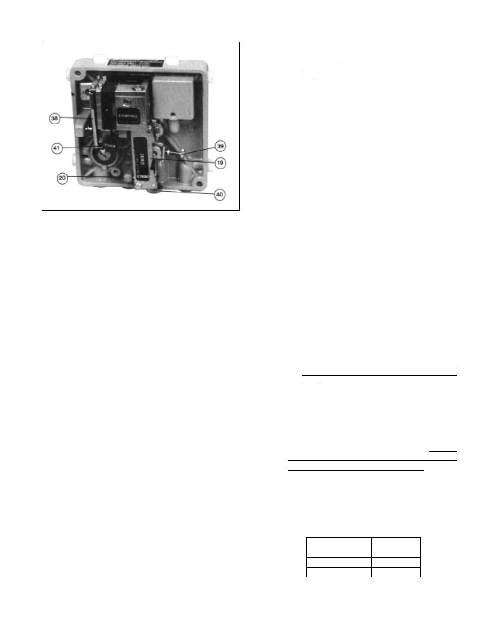
Press the flapper lever (38) several times to the
left and right until the flappers are correctly aligned.
f.
Set the minimum input “SIG” with the manual
loader; i.e. 9 psig for 9-15 psig, 11 psig for 11-15
psig.
g.
Turn zero thumbscrew (39) CW, increasing ten-
sion of range spring (41), until the actuator begins
to move away from its zero (shelf) position. (If
adjustment does not cause valve response, turn
off air supply (“IAS”) and return to 3.C. above;
increase the temporary spacer thickness in incre-
ments of 1/8” and repeat steps until the valve does
move). Care should be taken to assure that the
stroke factor lever (19) does not overtravel from
the starting point to the point where the stroke
factor lever (19) will hit the housing cover (WC),
before reaching its end position - approximately
39
°
rotation.
h.
Induce the maximum input “SIG” with the manual
loader; i.e. 15 psig for 9-15 psig or 11-15 psig.
i.
Turn the stroke factor thumbscrew (40) CW; this
shortens the valve stroke with respect to the “SIG”
change; i.e. less air pressure required to reach
valve’s maximum stroke position. Once valve
stem moves with each CW adjustment of the
stroke factor thumbscrew (40), reverse to CCW
rotation of stroke factor thumbscrew (40) and
precisely adjust up to the maximum stroke posi-
tion of the control valve.
j.
Repeat Steps e. and h. a minimum of three
times, as under this adjustment of Steps b.and
c. above, the STROKE and ZERO adjust-
ments are mutually dependent; i.e. interact-
ing.
k.
If procedures of Step 3 above have been
completed, skip Step 4 following, and go to
next paragraph V.B.
4.
Press the flapper lever (38) several times to the
left and right until the flappers are correctly aligned.
a.
Induce the minimum value of the input signal
(“SIG”) using a manual loader. (This corre-
sponds to the start of the valve’s stroke.)
b.
Turn the zero thumbscrew (39) either CW or
CCW until the actuator begins to cause valve
stem travel. Precisely adjust to the point where
travel just begins.
c.
Induce the maximum value of the input “SIG”.
(This corresponds to the end of the valve’s
stroke.)
d.
Turn the stroke factor thumbscrew (40) first
CCW until observing the shortening of the
valve’s stroke. Turn the stroke factor thumb-
screw (40) CW until the valve travel is pre-
cisely at its full stroke.
e.
Recheck the ZERO and STROKE
settings.They should be repeatable. Under
this procedure for adjustment, the ZERO and
STROKE calibrations are mutually indepen-
dent (i.e. non-interacting, when the feedback
lever (13) and travel stop pin (20) are properly
installed and positioned.
B. Setting GAIN: (See Figure 10)
1.
Increasing GAIN increases the sensitivity of the
positioner to a change in the input “SIG”. GAIN is
normally factory set when mounted by the factory,
and should not require field adjustment.
2.
The open loop gain varies with the supply “IAS”
pressure, and the values represent linear amplifi-
cation. Table 4 is a guide to the gain available for
each range spring (41) utilized:
Figure 9
Supply Pressure
Adjustable
(psig)
Range
20
150:1
35
125:1
TABLE 4