Fig. 5b model 964, Fig. 5c model 521, Fig. 6a – Cashco 9540L P/P User Manual
Page 4: Fig. 6b
IOM-9540L
4
4.
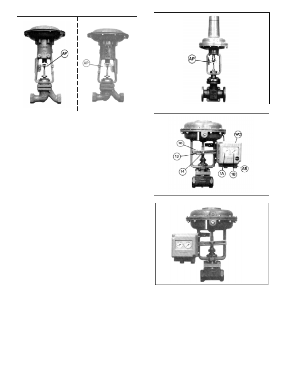
If the control valve does not have an accessory
plate (AP) installed, the actuator stem must be de-
coupled from the valve stem. (Refer to the valve/
actuator instructions for de-coupling procedure.)
Place accessory plate (AP) as indicated in Fig-
ures 5A, 5B or 5C.
5.
If it is necessary to re-orient an existing accessory
plate (AP) that is secured to the valve’s stem by a
jam nut, loosen the jam nut so that the accessory
plate (AP) is loosened enough that it can be tipped
and rotated to the proper frontal position. Re-
tighten the accessory plate (AP) jam nut. Attach
the stem feedback carrier bolt (14) to the acces-
sory plate (AP) using the Tinnerman nut.
(Note: Above is true for the 987 and 2296 actuators.
For Models 30, 55D, 55R, 115D and 115R actuators,
separate accessory plates are required for “left” or
“right” mounting positions.)
6.
Remove the positioner cover (WC). Orient the unit
so that the DAMPING & GAIN labels are top/
center, and the gauges (1A & 1B) are right side up.
7.
Fasten the positioner baseplate (BP) to the mount-
ing bracket (12) using the two mounting screws
(11) (See Figure 4).
8.
With the actuator at zero stroke (“LOAD” = 0 psig;
i.e. no air to actuator diaphragm), attach the
feedback lever (13) on the main shaft (17) (Figure
4) of the positioner with the feedback carrier bolt
(14) located in the feedback lever’s (13) slot. The
compensating spring (18) must be located above
the feedback carrier bolt (14) when the unit mount-
ing is on the right (See Figure 6A), and below the
feedback carrier bolt (14) when the mounting is on
the left. (See Figure 6B). Hand tighten socket cap
screw (21) (Figure 4); DO NOT WRENCH
TIGHTEN!
9.
Press the stroke factor lever (19) (See Figure 7) of
the positioner’s internals against the travel stop
pin (20) and hold firmly in place. Place the #5 Allen
wrench into the head of the socket cap screw (21),
and tighten while still holding stroke factor lever
(19). Tighten firmly. (A 5 mm, #5 metric Allen
wrench should be provided with the unit.)
10. Install tubing fittings with acceptable thread seal-
ant and tubing from the unit’s 1/4” NPT (female)
“OUTPUT 1” port of the adapter block(AB) up to
Figure 5B: (Model 964 w/left and right mounting positions)
Figure
6A
Figure 6B
Figure 5C: (Model 521 w/Model 30 actuator)