Iom-148 – Cashco Premier User Manual
Page 6
IOM-148
6
4. For ATO-FC valve action, it is necessary to
remove “stem windup” - use either a. or b.
a. Rotate manual handwheel operator
(MHWO) handwheel (58.1) ap prox i mate ly
1-3 revolutions CW (viewed from above
handwheel) until interconnecting arm and
stem linkage (5, 10) of actuator “relax”.
b. Pressurize actuator casing (1) only
until the in ter con nect ing arm and stem
linkage (5,10) “relax”. DO NOT OVER-
PRES SUR IZE.
NOTE: Do not remove the drive coupling ((32))
unless required.
5. Using a 7/16" allen key wrench, remove the
four sockethead cap screws (34) that secure
the cover plate ((13)) (13) to the arm housing
(4). Remove the cover plate ((13)) (13) by
pulling outwards.
6. Remove ball bearing (18) over shaft-end
(Rang er (7)), (Premier (3.2)).
7. Remove lock nut (46) that secures shoulder
bolt pin (40) through lever arms (5). Remove
shoulder bolt pin (40).
8. Units with Model 73N-B P/P Positioner or No
Positioner. Remove indicator spacer (17) by
sliding over end of shaft (Ranger (7)), (Pre mier
(3.2)).
9. Grasp lever arms and rotate stem (Ranger
(7)), (Pre mier (3.2)) as required to pull down
and away from the lower rod end-L.H. (9) to
allow clearance to remove arms (5). Slide
subassembly consisting of both arms (5),
spacer (12) or characterization cam (Model
73N-B (12)), and two spring pins (50) out wards
and away from the arm housing (4) and over
shaft-end (Ranger (7)), (Premier (3.2)).
10. While securely holding the actuator assembly
(AA) with an overhead sling support, and the
body assembly (BA) to prevent movement,
remove the four bolts (24) that secure the
body yoke (12) to the actuator arm housing
(4). Slide the actuator assembly (AA) over the
stem-end (Ranger (7)), (Pre mier (3.2)). Lay
body assembly (BA) aside.
C. Changing Actuator Mounting Position (With
No Change in Failsafe Action).
1. Determine the desired mounting position of
actuator assembly (AA) with respect to valve
body assembly (BA) from Figures 6-9, fol low-
ing pages.
2. The valve body/bonnet (1) to valve body
yoke (12) can be rotated in four 90° incre-
ments around the centerline of the valve shaft
(Rang er (7)) (Premier (3.2)).
3. Separate the actuator assembly (AA) from
the body assembly (BA) as described in this
Sec tion, V.B.1. through V.B.10.
4. Determine if it is necessary to interchange
packing studs (21) on Ranger or Premier
Un lined, and yoke (12) attachment studs (20)
on Ranger or Premier Unlined per fol low ing:
5. If required, remove both packing stud nuts
(22) on Ranger or Premier Unlined, and any
external live-loaded packing com po nents
(Rang er (27) (28) (29)), and set both aside
carefully to prevent an “inadvertent mix ing”
of the component’s “stack-up”.
6. Place matchmarks between yoke (12) and
valve bon net/body (1). While holding yoke
(12) with hand, remove yoke attachment stud
nuts (22)(Ranger and Premier Unlined qty =
2) (Premier EZO qty = 4). Move loose yoke
(12) over end of stem (Ranger (7)) (Premier
(3.2)) and set aside.
7. If necessary, remove all studs (20) (21) from
Ranger or Premier Unlined body assembly
(BA) and re lo cate/in ter change as re quired.
8. Reposition yoke (12) back onto body bonnet
(1), shifted/rotated the number of degrees
re quired (i.e. 90°, 180° or 270°), using the
matchmarks to guide to correct position. Se-
cure yoke (12) to body bonnet (1) by engaging
two yoke at tach ment nuts (22) on Ranger and
Premier Unlined, and four nuts (22) on Pre mier
EZO. Torque per following:
3" & 4" Rangers — 35-40 ft-lbs (47-54 N-m)
All Others — 75-80 ft-lbs (101-108 N-m).
9. Reposition packing fl ange (Ranger (14))
(Pre mier Unlined (5)) over packing studs (21)
for Ranger and Premier Unlined. Reinstall
live-loaded packing components (Rang er (27)
(28) (29) 2 sets). Reengage both pack ing stud
nuts (22) for Ranger and Premier Un lined. Set
torque level on pack ing stud nuts as indicated
in IOM-Ranger QCT, IOM-Pre mier EZO, or
IOM-Premier Unlined body as sem bly (BA)
instructions.
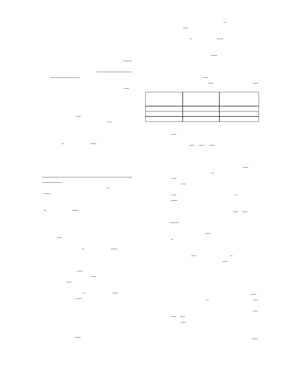
Rotary Valve
Degrees
Rotation
Position Change
Packing Studs
Yoke Attach Studs
Switch of Position
Ranger
90˚, 270˚
Required
Premier Unlined
180˚
Not Required
Premier EZO
90˚, 180˚, 270˚
Not Required