Warning, Iom-148 – Cashco Premier User Manual
Page 10
IOM-148
10
10. Reorient body assembly (BA) with respect to
the actuator assembly (AA). Rejoin the body
assembly (BA) to the actuator assembly (AA)
as described in this section, V.I. Ensure prop er
plug (Ranger (6)) or disc (Premier (3.1)) po si tion
prior to reinstalling lever arms (5). Ensure that
the lever arms (5) are “centered” within the arm
housing (4), and with respect to the actuator
stem linkage (8) (9) (10) (43) (44).
11. Recalibrate the unit (AA) (BA) and its positioner
((PA)).
D. Changing Failsafe Action:
1. Model 148 actuator (AA) is fi eld-reversible for
failsafe action with no additional parts required.
2. It is possible that both of the following can occur
together for the degree of disassembly under-
taken:
a. Failsafe action reversed.
b. Change in actuator mounting position.
NOTE: This section will be limited to the pro ce dures
for 2.a. above. If 2.b. is also desired, then it will be
necessary to reference Sub sec tion C. here in for the
added procedural steps as required.
This subsection will thus be limited as in di cat ed as
follows (reference Figures 10– 11 herein for be gin-
ning and end graphic orientations).
NOTE: Valve stem always goes CW to
“close”, viewed from stem-end.
4. Separate the actuator assembly (AA) from
the body assembly (BA) as described in this
Sec tion, V.B.1. through V.B.10.
5. Rotate plug (Ranger (6)) or disc (Premier (3.1))
position 90° to new failsafe position.
6. Slide actuator assembly (AA) that has been
rotated 180° back over the stem-end (Ranger
(7)) (Premier (3.2)). Align bolt holes between
arm housing (4) and valve yoke (12).
7. Reengage bolting (24) securing arm housing
(4) to yoke (12). Torque bolting (24) to 30-35
ft-lbs (40-47 N-m).
8. Ensure that the reinstalled lever arms (5) are
also rotated 180° in the same reference as the
actuator as sem bly (AA) was rotated. (NOTE:
The repositioned arms (5) will appear to have
only changed relative position by 90° in an oth er
plane.) Ensure the lever arms assembly (5)
is “centered” within the arm housing (4), and
with respect to the actuator stem (8) (9) (10)
(43) (44).
9. Rejoin the body assembly (BA) to the actuator
as sem bly (AA) as described in this Section,
V.I.
E. Diaphragm
Replacement:
1. Place unit assembly (AA) (BA) onto a fl at work
bench with actuator upper casing (1) on top
side; i.e. handwheel (58), if supplied, on top
side. Place a matchmark between actuator
casings (1) (2).
2. Ensure that all air pressure is released from
actuator assembly (AA) casing (1).
3. Ensure that manual handwheel (58) operator
is fully rotated upwards by loosening locking
lever (59) and ro tat ing CCW (viewed from top
side) as far as possible.
SPRING UNDER COMPRESSION. Prior to re mov ing
fl ange bolting (27, 28, 41, 42) re lieve range spring
(11) compression by rotating the handwheel or
adjusting screw assembly (58) CCW (viewed from
above handwheel (58) until all spring com pres sion
is re lieved. Fail ure to do so may result in fl ying
parts that could cause personal injury.
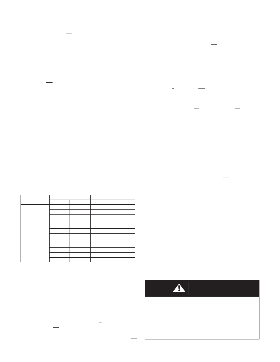
Product
Begin
End
Position
Action
Position
Action
Ranger QCT
“A”
ATO-FC
“B”
ATC-FO
“C”
ATO-FC
“D”
ATC-FO
“E”
ATO-FC
“F”
ATC-FO
“G”
ATO-FC
“H”
ATC-FO
“B”
ATC-FO
“A”
ATO-FC
“D”
ATC-FO
“C”
ATO-FC
“F”
ATC-FO
“E”
ATO-FC
“H”
ATC-FO
“G”
ATO-FC
Premier EZO
or
Premier
Unlined
“A”
ATO-FC
“B”
ATC-FO
“C”
ATO-FC
“D”
ATC-FO
“B”
ATC-FO
“A”
ATO-FC
“D”
ATC-FO
“C”
ATO-FC
WARNING
3. To reverse actuator (AA) failsafe action ba si cal ly
requires:
a. Moving lever arms (5) from left side of valve’s
stem (Ranger (7)) (Premier (3.2)) to right
side, or vice versa. This is ac com plished by
removing actuator assembly (AA) from body
assembly (BA) and ro tat ing actuator (AA)
180° about the ac tu a tor’s stem linkage (8)
(9) (10) (43) (44).
b. Rotating plug (Ranger (6)) or disc (Pre mier
(3.1)) by 90°; ie. from “closed” po si tion to
“open” position, or vice versa.
c. Reconnecting actuator (AA) to body (BA)
with lever arms (5) also rotated 180°.