English, 3 electrical connections, 2 main components – CAME BX-243 Kit User Manual
Page 10
10
ENGLISH
T
h
e d
at
a a
n
d i
n
fo
rm
at
io
n s
h
ow
n i
n
t
h
is
d
ia
lo
g
u
e m
ay b
e c
h
an
g
ed by C
am
e C
an
ce
ll
i A
u
to
m
at
ic
i S
.p
.A
. a
t a
n
y t
im
e w
it
h
o
u
t p
ri
o
r w
ar
ning
.
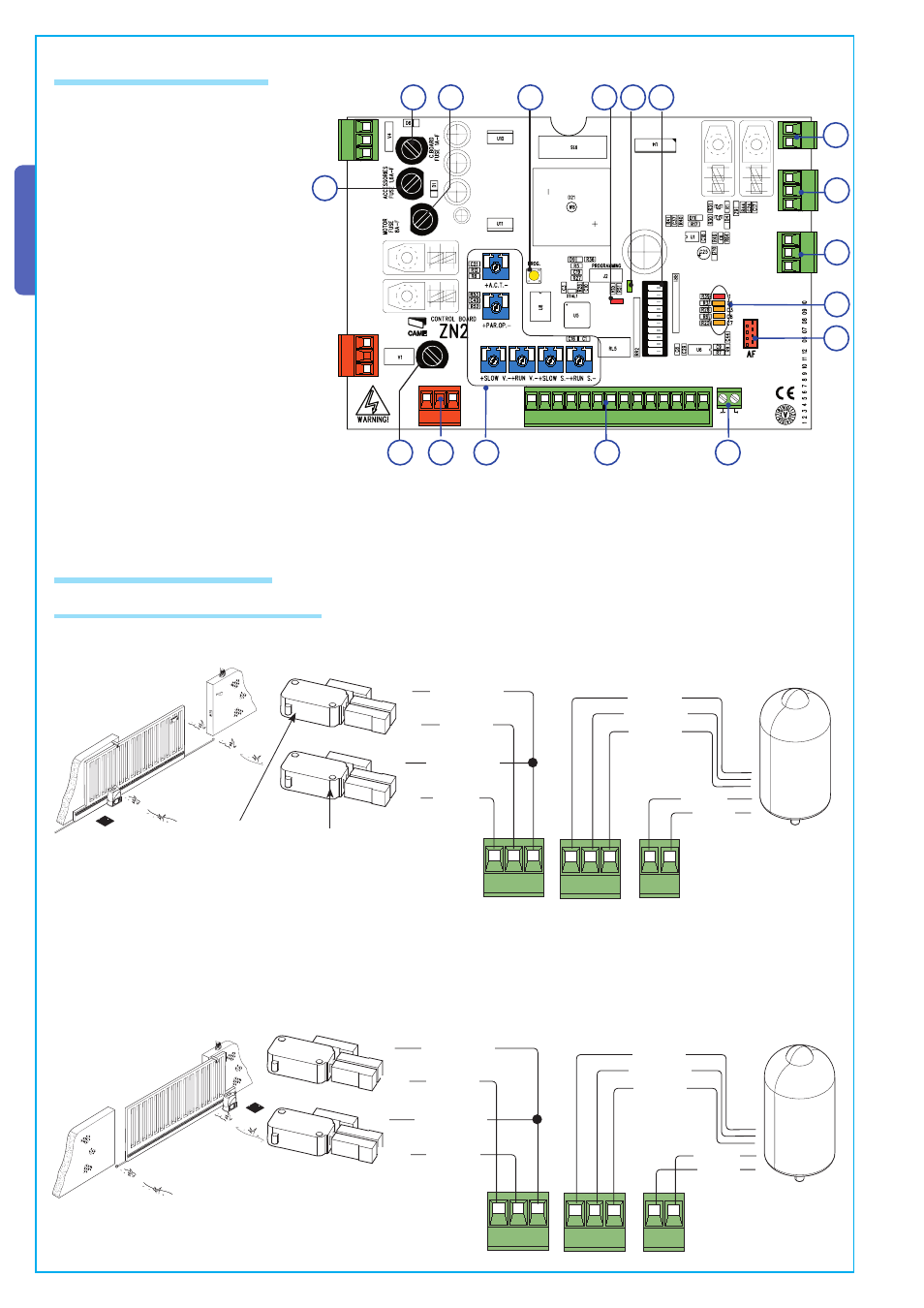
6.3 Electrical connections
24V (d.c.) motor
with encoder
Closing micro-
switch
COM
NC
NC
COM
Gearmotor, endstop and encoder
Modifications to the electrical connections for right-hand installations
Invert the gearmotor (M-N) and (FA-FC) endstop phases.
-
&#
Orange
Orange
White
Red
White
Brown
Green
Red
Green
-
&#
Orange
Orange
White
Red
White
Brown
Green
Red
Green
Opening micro-
switch
COM
NC
NC
COM
1) Power supply terminals
2) Endstop terminals
3) Motor terminals
4) Encoder terminals
5) Accessory fuse
6) Card fuse
7) Button for memorising the radio code
8) Radio-code signalling LED indicator
9) 230V-power signalling LED
10) Control and signalling LED group
11) Function selector DIP switch
12) Socket for connecting the remote
control’s radiofrequency card
13) Antenna terminal
14) Accessories’ and command device’s
terminals
15) Motor fuse
16) Line fuse
17) Setting trimmer
-.
,
.
/.
,
4
,
4
% 0
# # # # 43
%
&#
&!
&
072
,).%
6.2 Main components
2
4
3
10
7
8
9
5
6
11
12
17
13
14
15
16
1
Description of the standard electrical connections for left-hand installations